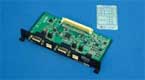
OP-SB88 FlexRay Communications Expansion Kit
Outline
The FlexRay communication is anticipated as a next-generation high-speed in-vehicle network.
The OP-SB88 is an expansion kit that allows monitoring of FlexRay communications on up to two channels in real time.
The kit incorporates a monitor function that does not require complicated parameter settings, and a simulation function with which the OP-SB88 works as a FlexRay communications node to transmit and receive data, thus powerfully supporting the initial development.
The filter function and high-capacity memory greatly shorten the analysis time of trouble.
Furthermore, it incorporates a simultaneous measurement function for external signals, which makes it possible to investigate the relationship between the operation of peripheral devices and communications data.
Features
10Mbps, 5Mbps, 2.5Mbps Communication Speed
Supports 10Mbps, 5Mbps, 2.5Mbps which are the standard speed of FlexRay communication.
Easy Monitoring
It enables to measure FlexRay data only by choosing a communication speed without setting about 50 parameters particular to FlexRay.
Dual Controller
Two FlexRay controllers equipped with OP-SB88 act for the leading cold start node and following cold start node that are necessary for FlexRay communications. It enables to evaluate the module of the non-cold start node that does not perform cold start.
FlexRay Transceiver, TJA1080
It has TJA1080 from NXP Semiconductors which is the world's first FlexRay transceiver.
Monitor Function
< header display >  |
< payload display >  |
Reception Filter for Each Channel
The filtering of the reception frame can be set for frame ID, each indicator bit, and cycle counter in the frame header.
Simultaneous Measurement of External Signal
It measures/records signal voltage of target device connected to the external terminal of analyzer in analog and digital value when receiving a frame.
< analog value display >  |
< digital value display > |
Display Specific Data on Pointed Line
It displays the arbitrary data (Frame header, Payload) of specific frame in the pointed line and helps to analyze the larger amount of FlexRay data.
< Specific Data on Pointed Line Setting > |
< Display Specific Data on Pointed Line >  |
Event Counter Display
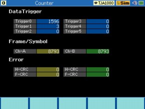
It displays the number of the frame reception of every channel, the number of matched data triggers, the number of the outbreak of each error. The appearance of the specific frame can be calculated by combining with the trigger function.
Trigger Function
It can set the data trigger for Payload data, frame ID, each indicator bit, and cycle counter in a frame. It also has the error trigger for communication error, and the external trigger for external input condition.
< list of trigger setting > |
< data trigger detail setting > |
(Example 1)
Count the matched triggers and display the number of appearance of each frame in the event counter.
(Example 2)
Load the result of trigger as external signal to the Oscilloscope.
< connecting for oscilloscope > |
< example at wave >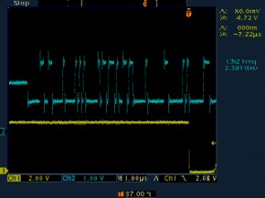 |
Simulation Funcition
It has two nodes to offer the evaluation environment of the non-cold start node to act for the movement of the FlexRay node. It is possible to have repeatedly automatic transmission of registered data and event transmission by key operation. It bring you the test environment demanded in initial development of FlexRay products.
Automatic Frame Transmission
Frame transmission of passive frame for media access with time trigger transmits frame data registered beforehand.
< list of automatic frame transmission >  |
< payload setting display > |
(Example 1)
Transmit frames when cycle counter is odd by specifying the cycle counter function.
(Example 2)
Transmit the arbitrary Payload for each cycle counter (0 to 63) by using the pattern table.
(Example 3)
Change the part of Payload by using the sweep function.
< pattern table> |
< sweep setting >  |
Event Transmission of Frame
Frame transmission function is made assuming the transmission of active frames for media access in event driven mode.
It can switch the transmission of frames (in the case of active frames) and Payload data by key operation. It transmits at most 16 Payload data for every frame.
< list of event send frame >  |
< payload allocation display >  |
Transmit FlexRay nodes by one click of the key.
Preset demo function loads the complicated parameters and able to transmit the two FlexRay nodes by one click of the key.
File Saving
A external memory (option) can store measured results and settings.
It enables to save the simulation settings including over 50 parameters particular to FlexRay. It contributes to improvement of the fieldwork in the demanded of quick correspondence.
Print Function
It can print all measured results and the simulation settings.
In addition, it is possible to load them as the plain text format in a external memory to use in a PC.
Example for monitor
*=[LE-8200]======[2013-02-21 9:37:58]=*
* Model     : LE-8200                 *
* Version   : 1.04                    *
* Extension : OP-SB88                 *
* Serial No.: ********                *
* Start time: 2013-02-21 09:37:18     *
* Stop time : 2013-02-21 09:37:21     *
*-------------------------------------*
*  PROTOCOL : FlexRay                 *
*  BUS SPEED: 10M                     *
*=====================================*

----TM-----CH--ID-CYC-PRE-NUL-SYN-STA-LEN-TSS-ST-HCRC--FCRC-I1234
000.034.997 A         --SYMBOL             35                0000
000.034.997 B         --SYMBOL             35                0000
000.035.169 A    4  0  0   0   1   1    2   5  G  097 433549 0000
000.035.176 B    4  0  0   0   1   1    2   5  G  097 256F4C 0000
000.038.168 A    4  1  0   0   1   1    2   5  G  097 044901 0000
000.038.176 B    4  1  0   0   1   1    2   5  G  097 621304 0000
000.041.168 A    4  2  0   0   1   1    2   5  G  097 CDCDD9 0000
000.041.175 B    4  2  0   0   1   1    2   5  G  097 AB97DC 0000
000.044.168 A    4  3  0   0   1   1    2   5  G  097 8AB191 0000
000.044.175 B    4  3  0   0   1   1    2   5  G  097 ECEB94 0000
000.047.088 A    2  4  0   0   1   1    2   5  G  4A9 20543D 0000
000.047.095 B    2  4  0   0   1   1    2   5  G  4A9 460E38 0000
000.047.168 A    4  4  0   0   1   1    2   5  G  097 03A9A2 0000
000.047.175 B    4  4  0   0   1   1    2   5  G  097 65F3A7 0000
000.050.088 A    2  5  0   0   1   1    2   5  G  4A9 672875 0000
000.050.095 B    2  5  0   0   1   1    2   5  G  4A9 017270 0000
000.050.168 A    4  5  0   0   1   1    2   5  G  097 44D5EA 0000
000.050.175 B    4  5  0   0   1   1    2   5  G  097 228FEF 0000
000.053.088 A    2  6  0   0   1   1    2   5  G  4A9 AEACAD 0000
000.053.095 B    2  6  0   0   1   1    2   5  G  4A9 C8F6A8 0000
000.053.168 A    4  6  0   0   1   1    2   5  G  097 8D5132 0000
000.053.175 B    4  6  0   0   1   1    2   5  G  097 EB0B37 0000
000.053.408 A   10  6  1   1   0   0    2   5  G  7A7 7565D8 0000
000.053.415 B   10  6  1   1   0   0    2   5  G  7A7 133FDD 0000
000.053.807 A   20  6  0   1   0   0    2   5  G  46B 9C4A32 0000
000.053.815 B   20  6  0   1   0   0    2   5  G  46B FA1037 0000
000.054.207 A   30  6  0   1   0   0    2   5  G  3AC DC91A7 0000
000.054.215 B   30  6  0   1   0   0    2   5  G  3AC BACBA2 0000
000.056.087 A    2  7  0   0   1   1    2   5  G  4A9 E9D0E5 0000
000.056.095 B    2  7  0   0   1   1    2   5  G  4A9 8F8AE0 0000
000.056.167 A    4  7  0   0   1   1    2   5  G  097 CA2D7A 0000
000.056.175 B    4  7  0   0   1   1    2   5  G  097 AC777F 0000
000.056.407 A   10  7  1   1   0   0    2   5  G  7A7 321990 0000
000.056.415 B   10  7  1   1   0   0    2   5  G  7A7 544395 0000
000.056.807 A   20  7  0   1   0   0    2   5  G  46B 2A6B9E 0000
000.056.814 B   20  7  0   1   0   0    2   5  G  46B 4C319B 0000
000.057.207 A   30  7  0   1   0   0    2   5  G  3AC C68024 0000
000.057.214 B   30  7  0   1   0   0    2   5  G  3AC A0DA21 0000
000.058.187 A   60  7  0   1   0   0    4   5  G  563 3CAD9B 0000
000.058.198 B   60  7  0   1   0   0    4   5  G  563 52B8AE 0000
000.059.087 A    2  8  0   0   1   1    2   5  G  4A9 E1F100 0000
000.059.094 B    2  8  0   0   1   1    2   5  G  4A9 87AB05 0000
000.059.167 A    4  8  0   0   1   1    2   5  G  097 C20C9F 0000
000.059.174 B    4  8  0   0   1   1    2   5  G  097 A4569A 0000
000.059.407 A   10  8  1   1   0   0    2   5  G  7A7 3A3875 0000
000.059.414 B   10  8  1   1   0   0    2   5  G  7A7 5C6270 0000
000.059.807 A   20  8  0   1   0   0    2   5  G  46B 1C46D7 0000
000.059.814 B   20  8  0   1   0   0    2   5  G  46B 7A1CD2 0000
000.060.207 A   30  8  0   1   0   0    2   5  G  3AC 5078B5 0000
000.060.214 B   30  8  0   1   0   0    2   5  G  3AC 3622B0 0000
000.062.087 A    2  9  0   0   1   1    2   5  G  4A9 A68D48 0000
000.062.094 B    2  9  0   0   1   1    2   5  G  4A9 C0D74D 0000
000.062.167 A    4  9  0   0   1   1    2   5  G  097 8570D7 0000
000.062.174 B    4  9  0   0   1   1    2   5  G  097 E32AD2 0000
000.062.407 A   10  9  1   1   0   0    2   5  G  7A7 7D443D 0000
000.062.414 B   10  9  1   1   0   0    2   5  G  7A7 1B1E38 0000
000.062.807 A   20  9  0   1   0   0    2   5  G  46B 3C923B 0000
000.062.814 B   20  9  0   1   0   0    2   5  G  46B 5AC83E 0000
000.063.207 A   30  9  0   1   0   0    2   5  G  3AC 4A6936 0000
000.063.214 B   30  9  0   1   0   0    2   5  G  3AC 2C3333 0000
000.064.187 A   60  9  0   1   0   0    4   5  G  563 2B90EF 0000
000.064.198 B   60  9  0   1   0   0    4   5  G  563 4585DA 0000
Example for FlexRay parameter
*=[LE-8200]======[2013-02-21 9:39:23]=*
*  PROTOCOL : FlexRay                 *
*  BUS SPEED: 10M                     *
*  WUS      : On                      *
*  MTS ChA  : Off                     *
*  MTS ChB  : Off                     *
*  Sub node : On                      *
*  WUS      : On                      *
*=====================================*

#### Cluster parameters

 gColdstartAttempts                : 4
 gdActionPointOffset               : 10
 gdCASRxLowMax                     : 76
 gdDynamicSlotIdlePhase            : 0
 gdMinislot                        : 20
 gdMinislotActionPointOffset       : 10
 gdStaticSlot                      : 40
 gdSymbolWindow                    : 100
 gdTSSTransmitter                  : 6
 gdWakeupSymbolRxIdle              : 59
 gdWakeupSymbolRxLow               : 54
 gdWakeupSymbolRxWindow            : 301
 gdWakeupSymbolTxIdle              : 180
 gdWakeupSymbolTxLow               : 60
 gListenNoise                      : 2
 gMacroPerCycle                    : 3000
 gMaxWithoutClockCorrectionFatal   : 15
 gMaxWithoutClockCorrectionPassive : 15
 gNumberOfMinislots                : 24
 gNumberOfStaticSlots              : 48
 gOffsetCorrectionStart            : 2600
 gPayloadLengthStatic              : 2
 gSyncNodeMax                      : 15

#### Main node parameters

 pAllowHaltDueToClock    : False
 pAllowPassiveToActive   : 0
 pClusterDriftDamping    : 4
 pdAcceptedStartupRange  : 1875
 pDecodingCorrection     : 36
 pDelayCompensationChA   : 0
 pDelayCompensationChB   : 0
 pdListenTimeout         : 240722
 pdMaxDrift              : 361
 pExternOffsetCorrection : 0
 pExternRateCorrection   : 0
 pKeySlotId              : 4
 pKeySlotUsedForStartup  : True
 pKeySlotUsedForSync     : True
 pLatestTx               : 23
 pMacroInitialOffsetChA  : 11
 pMacroInitialOffsetChB  : 11
 pMicroInitialOffsetChA  : 4
 PMicroInitialOffsetChB  : 4
 pMicroPerCycle          : 120000
 pMirocPerMacroNom       : 40
 pOffsetCorrectionOut    : 1122
 pPayloadLengthDynMax    : 4
 pRateCorrectionOut      : 722
 pSingleSlotEnabled      : False
 pWakeupChannel          : Ch-A
 pWakeupPattern          : 4

#### Sub node parameters

 pKeySlotId              : 2

#### Auto send table

 ** No. 0 **
  Frame ID      : 10
  Channel       : Both
  Preamble      : 1
  Payload       : 0102 0304

 ** No. 1 **
  Frame ID      : 20
  Channel       : Both
  Preamble      : 0
  Sweep
   Endian       : Big
   Size         : 16 bit
   Position     : 0
   Initial      : +0
   Time1        : 1000
   Value1       : +1000
   Time2        : 2000
   Value2       : +3000
   Time3        : 6000
   Value3       : +0
  Payload       : 0000 0000

 ** No. 2 **
  Frame ID      : 30
  Channel       : Both
  Preamble      : 0
  Pattern       : 0

#### Event send table

 ** No. 0 **
  Frame ID      : 50
  Channel       : Both
  Preamble      : 0
  One shot send : On
  Payload (0)   : 0050 0000 0000 0000
  Payload (1)   : 0050 0001 0000 0000
  Payload (2)   : 0050 0002 0000 0000
  Payload (3)   : 0050 0003 0000 0000
  Payload (4)   : 0050 0004 0000 0000
  Payload (5)   : 0050 0005 0000 0000
  Payload (6)   : 0050 0006 0000 0000
  Payload (7)   : 0050 0007 0000 0000
  Payload (8)   : 0050 0008 0000 0000
  Payload (9)   : 0050 0009 0000 0000
  Payload (A)   : 0050 000A 0000 0000
  Payload (B)   : 0050 000B 0000 0000
  Payload (C)   : 0050 000C 0000 0000
  Payload (D)   : 0050 000D 0000 0000
  Payload (E)   : 0050 000E 0000 0000
  Payload (F)   : 0050 000F 0000 0000

 ** No. 1 **
  Frame ID      : 60
  Channel       : Both
  Preamble      : 0
  Cycle interval: 2
  Cycle base    : 1
  Payload (0)   : 0060 0000 0000 0000
  Payload (1)   : 0060 0001 0000 0000
  Payload (2)   : 0060 0002 0000 0000
  Payload (3)   : 0060 0003 0000 0000
  Payload (4)   : 0060 0004 0000 0000
  Payload (5)   : 0060 0005 0000 0000
  Payload (6)   : 0060 0006 0000 0000
  Payload (7)   : 0060 0007 0000 0000
  Payload (8)   : 0060 0008 0000 0000
  Payload (9)   : 0060 0009 0000 0000
  Payload (A)   : 0060 000A 0000 0000
  Payload (B)   : 0060 000B 0000 0000
  Payload (C)   : 0060 000C 0000 0000
  Payload (D)   : 0060 000D 0000 0000
  Payload (E)   : 0060 000E 0000 0000
  Payload (F)   : 0060 000F 0000 0000

#### Pattern data table

 ** No. 0 **
  Cycle  0 : 0030 0000
  Cycle  1 : 0030 0001
  Cycle  2 : 0030 0002
  Cycle  3 : 0030 0003
  Cycle  4 : 0030 0004
  Cycle  5 : 0030 0005
  Cycle  6 : 0030 0006
  Cycle  7 : 0030 0007
  Cycle  8 : 0030 0008
  Cycle  9 : 0030 0009
  Cycle 10 : 0030 000A
  Cycle 11 : 0030 000B
  Cycle 12 : 0030 000C
  Cycle 13 : 0030 000D
  Cycle 14 : 0030 000E
  Cycle 15 : 0030 000F
  Cycle 16 : 0030 0010
  Cycle 17 : 0030 0011
  Cycle 18 : 0030 0012
  Cycle 19 : 0030 0013
  Cycle 20 : 0030 0014
  Cycle 21 : 0030 0015
  Cycle 22 : 0030 0016
  Cycle 23 : 0030 0017
  Cycle 24 : 0030 0018
  Cycle 25 : 0030 0019
  Cycle 26 : 0030 001A
  Cycle 27 : 0030 001B
  Cycle 28 : 0030 001C
  Cycle 29 : 0030 001D
  Cycle 30 : 0030 001E
  Cycle 31 : 0030 001F
  Cycle 32 : 0030 0020
  Cycle 33 : 0030 0021
  Cycle 34 : 0030 0022
  Cycle 35 : 0030 0023
  Cycle 36 : 0030 0024
  Cycle 37 : 0030 0025
  Cycle 38 : 0030 0026
  Cycle 39 : 0030 0027
  Cycle 40 : 0030 0028
  Cycle 41 : 0030 0029
  Cycle 42 : 0030 002A
  Cycle 43 : 0030 002B
  Cycle 44 : 0030 002C
  Cycle 45 : 0030 002D
  Cycle 46 : 0030 002E
  Cycle 47 : 0030 002F
  Cycle 48 : 0030 0030
  Cycle 49 : 0030 0031
  Cycle 50 : 0030 0032
  Cycle 51 : 0030 0033
  Cycle 52 : 0030 0034
  Cycle 53 : 0030 0035
  Cycle 54 : 0030 0036
  Cycle 55 : 0030 0037
  Cycle 56 : 0030 0038
  Cycle 57 : 0030 0039
  Cycle 58 : 0030 003A
  Cycle 59 : 0030 003B
  Cycle 60 : 0030 003C
  Cycle 61 : 0030 003D
  Cycle 62 : 0030 003E
  Cycle 63 : 0030 003F
Technical Support
To receive supports of OP-SB88 from LINEEYE, customers need to apply “OP-SB88 Commercial Support Application”.
The only person who apply it can ask technical question regarding to OP-SB88 through Email or FAX, and receive information of OP-SB88 (update information etc.)
DOWNLOAD OP-SB88 Support Appication.doc
Specification
| Interface | FlexRay V2.1A |
|---|---|
| Transceiver | TJA1080 or RS-485 ( equivalent to SN65HVD3088E ) selectable from the analyzer |
| Measured Channel | 2 channels (A and B) |
| Speed | 10Mbps, 5Mbps, 2.5Mbps A/B channel |
| Monitor Function | Saves FlexRay data per frame. Displays following objects on several kinds of mode : Header/ Payload(0 to 254 bytes) / Trailer Segment , CAS Symbol |
| Error Check | Header CRC error/ Frame CRC Error, It is possible to display CRC value |
| Time Stamp | 9 digits. Diaplays the time between the start of measuement and the point of receiving a frame, or the time between the received frames in 1mS or 100μS or 10μS or 1μS unit. |
| Capture Memory | Capacity : 100MB (Data is saved to the capturing memory of the analyzer.) Two separated screens. Data can be used as ring buffer or fixed size buffer. |
| Auto Save Function | Automatically saves the monitored data as communications log file in the external memory.*1 |
| Display format | Frame display, Payload display, External signal voltage display, Display specified frames at the fixed position |
| Counter function | Counts trigger conditions, received frame, Header CRC error and Frame CRC error (max. 6 digits). |
| Filter Function | Saves/displays only the specific frames matched with following conditions : Each bit of channel or indicator, specific ID, specific cycle counter |
| Trigger Function | Automatically stops measuring when the following conditions are found. Data (6 sets) : Appointment Channel, Indisator, ID, Cycle Counter, specific Payload Data in the frame(max.16 data, Don't care and Bitmask can be selected) Error (1 set) : Header CRC Error / Frame CRC Error External Input (1 set) : The falling edge of the extrernal trigger input |
| Simulation Function | Can transmit the data registered previously or the presetting data. Can transmit the startup fame or the synchronous frame(up to 2 nodes) Can point the preamble indicator. Can transmit the wakeup symbol (WUS). |
| Transmitting Payload | Data length : 0 to 254 bytes Max. 784 kinds of transmitting Payload can be registered.*2 |
| Continuous transmission | Up to 16 kinds of data can continuously send. Data is with Channel, ID, Cycle counter and Payload (It is possible that a part of the data can automatically sweep at the designated condition). Or data with Channel, ID and Pattern (selected from at most 8 patterns that are designated the Payload per communication cycle). |
| Event Transmission | Can transmit registered frames by the key operation. (continuously or one-shot) The frames include the data of Channel, ID, Cycle counter. Up to 16 kinds of frames can be resigted and each one has 8 kinds of Payload. |
| External Signal Input | Measures the logic conditions and voltate (range: -15 to +15V) of Input of four external signals (max. input: -25 to +25V) on the timing of receiving frames, and saves it to the memory with the frame data. Also displays it on the LCD / LEDs at real-time. |
| External Trigger input/output | Input of external trigger: 1, Output of external trigger: 1, Both on TTL level |
| Componets | Expansion board, Firmware CD, Line state sheet(B), Two DB9 monitor cables, Two 3-line-probe cable, 8-line-probe cable |