(For LE-8200A/8200)
OP-SB87
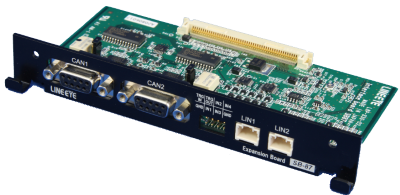
OP-SB87 is an expansion board for CAN/LIN communications, inserting into a slot of communication analyzer LE-8200A/LE-8200. It has 2 CAN connectors and 2 LIN connectors, and measures 2 channels of CAN or LIN, or 1 CAN/1 LIN. It is useful to measure network where there are CAN and LIN communications at the same time.
Monitor function enables to display data at real time, capturing CAN/LIN data into the memory. And, simulation function enables to test transmission/ reception acting as the counterpart to the target device. Powerful ID filter function and trigger function make a sufficient analysis. 4 external signals can be measured as digital or analog signals simultaneously with the communications data.
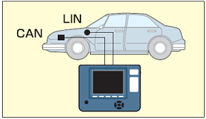
Usage image
Easy setup for a CAN/LIN analyzer !!
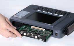
As the measurement firmware is pre-installed to the analyzer, it can be used as a stand-alone analyzer that supports CAN/LIN communication simply by replacing the interface board.
Exchanging the boards
The line state sheet for the measurement target is attached. It fits snugly into the line-state LED part of the analyzer.

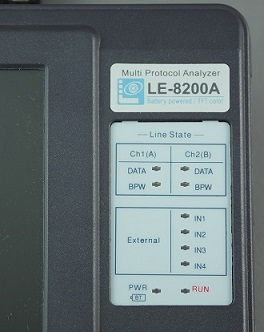
| Description | LED | Bus Level | Meaning |
|---|---|---|---|
| DATA | ON | Dominant | Turns on the light corresponding to the bus level of CAN/LIN. |
| OFF | Recessive | ||
| BPW | ON | About 10V | Inputs (9V to 18V) from 9pin for CAN interface, or LIN Vbat (9V to 18V) |
| OFF | Under 3V | ||
| IN1-IN4 | ON | Above 2.3V | External Input (-15 to +15V) |
| OFF | Under 1.0V |
Operating Instructions
Preparation
The OP-SB87 firmware is already installed in the LE-8200A / LE-8200. After inserting the expansion board into the analyzer and turning on the analyzer, OP-SB87 firmware will automatically start. To measure the standard interface of RS-232C, you can simply exchange to the RS-232C/RS-422/RS-485 board without exchanging the firmware.
At "Interface" setting, select 2 channels for monitoring and 1 channel for simulation. To monitor high-speed CAN (ISO11898), set the terminal control (on/off) on the expansion board using the jumper pin.
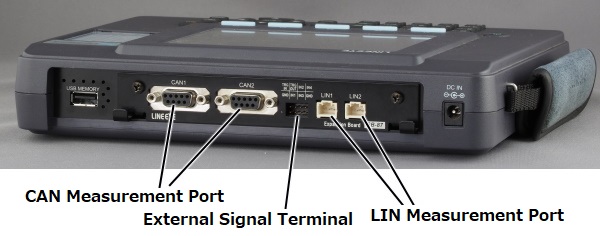
Connection
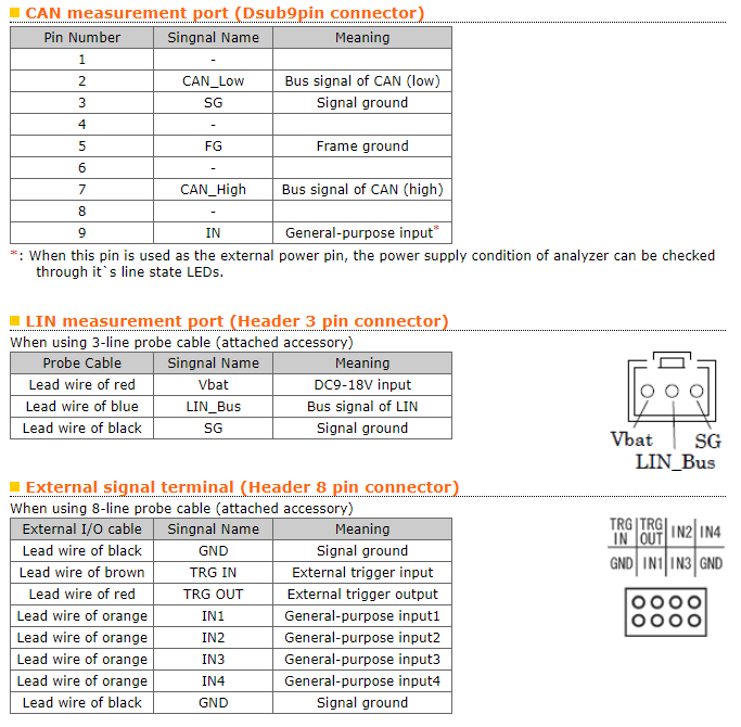
For CAN, connect the target CAN BUS using the included monitor cable. For LIN, connect to the LIN BUS using the included 3-lines probe cable.
< Example of CAN measurement >
< Example of LIN measurement >
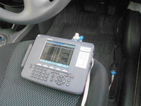
Image of CAN monitoring by OP-SB87 using the optional cable "OBD2-DSUB9" for OBD2 connector of a car.
Monitor Function
This equipment measures CAN/LIN data and voltage of four external signals at the same time. Since measurement data is recorded with time stamp (Min. resolution: 1us), error timing and transferring cycle are easily checked. Also, ID filter, which displays specific frames, makes it possible to have a sufficient analysis.
CAN Monitor
Support CAN 2.0B which contains 11bit ID and 29bit ID frames. It is possible to set either Low-speed CAN or High-speed CAN transceiver IC for each channel, and set any arbitrary speed and specify the timing of inserting a bit.
< Setting of speed, bit timing, and ID filter >
LIN Monitor
Support LIN specification Rev1.1, 1.2, 1.3, 2.0, 2.1. It is possible to set calculation method of data length Checksum for each ID, and define the frame end by idle time.
< LIN Configuration >
< Data length & Checksum >
Monitoring CAN/LIN Simultaneously
Display measured data at real time. Display mode is selectable by one press of a key.
< Measured Data >
Display measured data on channel 1 and 2 in time series.
| Display | Meaning |
|---|---|
| Time | Displays the time when the frame is received at the unit selected at "Record control". (e.g. : When "MS1ms" is selected and displays 042:16:898, that means frame was received at 42 minuts and 16.898 seconds.) |
| ΔTime | Displays the difference of time stamps compared to the previous time stamp. ( does not display the difference of time stamps compared to the beggining of time stamp. ) "Time" and "rTime" can be changed by pressing [F5]. |
| CH | Displays the channel received. (1:CH1, 2:CH2) |
| (Br-Sy-)ID | At the time of CAN, displays the ID of the frame received. At the time of LIN, displays the bit number of "Syncbreakno", and the values of "Syncfield" and "Identifer" in hex. |
| Type | Displays a type of the frame received. |
| DL | At the time of CAN, displays the contents of data length code in decimal. At the time of LIN, displays the data length which is set by Configuration. |
| St | Displays whether the condition of the frame is normal or abnormal. |
| Data | Displays the contents of the data field in hex. |
| I1234 | Displays the status of the external input in binary. (0=Low, 1=High) |
| FC | Displays the contents of CRC in CAN, or the contents of checksum in LIN. By pressing [F3], "l1234" and "FC" are changed. |
< Voltage Data >
Display voltage of four external signals in time series.
< Watch Data >
Display specific ID frame at an appointed place. Specify the target ID and appoint the place to display.
Analog Measurement Mode (Ver1.07 or above)
On-line mode measures voltage of four external signals at the time of monitoring CAN/LIN data. Analog mode measures voltage of four external signals at specific sampling time and can be used as an Analog data logger. Measurement data can be saved in the external memory as a text format.
< Display voltage of four external signals >
< Data displayed in spreadsheet software >
Trigger
Up to 8 pairs of trigger condition and action can be specified. It can be used as a sequential trigger, which enables another trigger conditions as satisfied action of some trigger conditions. Therefore, it is useful for intermittent analysis of troubles.
< Trigger Setup Summary >
< Trigger Setting >
FACTOR
| Contents | |
|---|---|
| ERROR | Executed the trigger by an error of LIN. BREAK : Considers as an error when Dominant of BREAK field is 10 bit. SYNC : Considers as an error when the value of SYNC field is other than 55(h). PARITY : Parity Error CHECKSUM : Checksum Error FRAMING : Framing Error (When the stop bit is Dominant.) |
| DATA | Executes the trigger when the specific data frame is received. Sets for the receiving channel, ID, and the contents of the data field. (Settable for DON'T CARE and a bit mask.) |
| REMOTE | Executes the trigger when the specific remote frame of CAN is received. Sets for the receiving channel and ID. (Settable for DON'T CARE and a bit mask.) |
| TM/CT | Executes the trigger when the timer or the counter reaches the value being set. SelectsTM0/TM1 or CT0/CT1. |
| TRG IN | Executes the trigger by status of TRG IN. |
| EXTERNAL | Executes the trigger by an external trigger input. Sets RISING or FALLING. |
ACTION
| Contents | |
|---|---|
| BUZZER | Sounds for about 0.3 seconds. |
| STOP | Stops the measurement. Sets the time from the occurrence of the trigger to the stop of the measurement as OFFSET. * QUICK: Stops the measurement immediately. * BEFORE: Stops the measurement after taking some data following the trigger. * CENTER: Stops the measurement so that same amount of data is taken in before and after the trigger. * AFTER: Stops the measurement after taking in a large amount of data after the trigger. |
| SAVE | Save data of before and after the trigger specified by the OFFSET when the trigger is specified. |
| TIMER | Control the timer. Sets the kind of the timer and the contents of the control. * START: Starts the timer. * STOP: Stops the timer. * RESTART: Clears and restarts the timer. |
| COUNTER | Control the counter. Sets the kind of the counter and the contents of the control. * INCREMENT: Adds 1 to the counter. * CLEAR: Sets 0 for the counter. |
| TRIG SW | Controls another trigger state. * DISABLE: Sets invalid for the trigger. * ENABLE: Sets valid for the trigger. * CHANGE: Changes the trigger state. DTSABLE « ENABLE |
| SEND | Executes the control of the data which is set on the transmission data table. Sets transmission data table, the contents of the control (Transmit or Stop), and the time (RESPONSE) from the occurrence of the trigger to the control. (It is effective only at CAN.) |
| TRG OUT | Outputs Low pulse (1ms) to the external trigger (TRG OUT). |
Simulation
CAN
The simulation function enables to transmit data frame and remote frame of standard/expansion format with one click of a key. It is possible to register a part of data as the sweep data and transmit the amended sweep data at appointed time in order. Those functions are very useful for development of CAN BUS and DeviceNet equipment.
< Data Table Setup Screen >
< CAN Data Table Screen >
< Sweep Data Setup Screen >
New function on firmware version 1.09
One main table and sixteen kinds of sub tables becomes one group. And, the group of 17 tables in total can be sent by one press of a key in the Manual simulation.
| Main table | Sub table | Group | |||
|---|---|---|---|---|---|
| Table 0 | Table 0-0 | Table 0-1 | ··· | Table 0-F | Table 0 Group |
| Table 1 | Table 1-0 | Table 1-1 | ··· | Table 1-F | Table 1Group |
| : | : | : | : | : | : |
| Table F | Table F-0 | Table F-1 | ··· | Table F-F | Table F Group |
< CAN Data table Summary (Main) >
< CAN table0 subtable Summary >
< Setting of sutable0-0 in data table0 >
Configurations of sub tables include “on/off”(valid/invalid of sub tables) and “delay” settings beside the same configurations with main tables. Following is the example of transmission.
< Monitor screen when simulating subtable >
LIN
Supports both Master and Slave.
< Master Mode Screen >
Set the response space (space between header and response) at 0-99 bits.
< Slave Mode Screen >
Inter byte space (space between response data) at 0-99 bits.
Register header and response frames on the LIN data tables (16 tables).
< Data table summary >
< Data table setting >
At the time of Master, it is possible to transmit the data repeatedly or in order, or transmit specific schedule number by key operation. You can set Parity error, numbers of bit in the BREAK field, and error data in the SYNC field in each schedule number.
At the time of Slave, transmits when matching ID set to the data table. Also, it is possible to transmit Wake-up signal (80h) by pressing [x] key while simulation.
< Master Mode Screen >
< Schedule Setup Screen >
Transmit in the order of table0->F->1->2.
Table F includes 18bit in the BREAK field
and Parity error.
Support Logic Analyzer Analysisト
The logic analyzer operates at a sampling rate up to 100MHz*1, and able to analyze the timing of CAN/LIN signals and external signals. Waveform vision helps to identify hardware problems. You can also use it for education purposes.
< Logic analyzer screen >
Data Use
Search Function
It is possible to search the specific frame of Data and Time stamp.
Print Data
It is possible to print measured data and data tables.
Measured Data
*=[LE-8200]=====[2013-01-28 12:02:00]=* * Model : LE-8200 * * Version : 1.08 * * Extension : OP-SB87 * * Serial No.: ******** * * Start time: 2013-01-28 12:00:00 * * Stop time : 2013-01-28 12:01:00 * *-------------------------------------* ----TM------CH------ID--TYPE--DLC-ST-----DATA---------FC--I1234 08:02:022 1 003 DAT 3 G 3333FF 0100 08:02:098 1 021 REM 6 G 0100 08:02:166 2 13-55-3F FRM G 01230456789A 6E 0100 08:02:407 1 002 DAT 8 G 00000000005414FF 0100 08:02:476 1 00000006 DAT 4 G 00006666 0100 08:02:624 1 004 DAT 4 G 01004444 0100 08:02:631 1 00000022 REM 8 G 0100 08:02:709 1 016 DAT 3 G 818011 0100 08:02:936 1 00000008 DAT 4 G FD028888 0100 08:03:006 1 1FE00001 DAT 3 G 550555 0100 08:03:022 1 003 DAT 3 G 3333FF 0100 08:03:098 1 021 REM 6 G 0100 08:03:166 2 13-55-3F FRM G 01230456789A 6E 0100 08:03:381 1 7FE REM 6 G 0100 08:03:407 1 002 DAT 8 G 00000000005414FF 0100 08:03:476 1 00000006 DAT 4 G 00006666 0100 08:03:624 1 004 DAT 4 G 01004444 0100 08:03:631 1 00000022 REM 8 G 0100 08:03:710 1 016 DAT 3 G 818011 0100 08:03:936 1 00000008 DAT 4 G FD028888 0100 08:04:006 1 1FE00001 DAT 3 G 550555 0100 08:04:022 1 003 DAT 3 G 3333FF 0100 08:04:098 1 021 REM 6 G 0100 08:04:166 2 13-55-3F FRM G 01230456789A 6E 0100 08:04:407 1 002 DAT 8 G 00000000005414FF 0100 08:04:476 1 00000006 DAT 4 G 00006666 0100 08:04:624 1 004 DAT 4 G 01004444 0100 08:04:631 1 00000022 REM 8 G 0100 08:04:709 1 016 DAT 3 G 818011 0100 08:04:936 1 00000008 DAT 4 G FD028888 0100 08:05:006 1 1FE00001 DAT 3 G 550555 0100 08:05:022 1 003 DAT 3 G 3333FF 0100 08:05:098 1 021 REM 6 G 0100 08:05:166 2 13-55-3F FRM G 01230456789A 6E 0100 08:05:381 1 7FE REM 6 G 0100 08:05:407 1 002 DAT 8 G 00000000005414FF 0100 08:05:476 1 00000006 DAT 4 G 00006666 0100 08:05:624 1 004 DAT 4 G 01004444 0100 08:05:631 1 00000022 REM 8 G 0100 08:05:710 1 016 DAT 3 G 818011 0100 08:05:936 1 00000008 DAT 4 G FD028888 0100 08:06:006 1 1FE00001 DAT 3 G 550555 0100 08:06:022 1 003 DAT 3 G 3333FF 0100 08:06:098 1 021 REM 6 G 0100 08:06:166 2 13-55-3F FRM G 01230456789A 6E 0100 08:06:407 1 002 DAT 8 G 00000000005414FF 0100 08:06:476 1 00000006 DAT 4 G 00006666 0100 08:06:624 1 004 DAT 4 G 01004444 0100 08:06:631 1 00000022 REM 8 G 0100 08:06:709 1 016 DAT 3 G 818011 0100 08:06:936 1 00000008 DAT 4 G FD028888 0100 08:07:006 1 1FE00001 DAT 3 G 550555 0100 08:07:022 1 003 DAT 3 G 3333FF 0100 08:07:098 1 021 REM 6 G 0100 08:07:166 2 13-55-3F FRM G 01230456789A 6E 0100 08:07:381 1 7FE REM 6 G 0100 08:07:407 1 002 DAT 8 G 00000000005414FF 0100 08:07:476 1 00000006 DAT 4 G 00006666 0100 08:07:624 1 004 DAT 4 G 01004444 0100 08:07:631 1 00000022 REM 8 G 0100 08:07:710 1 016 DAT 3 G 818011 0100 08:07:936 1 00000008 DAT 4 G FD028888 0100 08:08:006 1 1FE00001 DAT 3 G 550555 0100 08:08:022 1 003 DAT 3 G 3333FF 0100 08:08:098 1 021 REM 6 G 0100 08:08:165 2 13-55-3F FRM G 01230456789A 6E 0100 08:08:407 1 002 DAT 8 G 00000000005414FF 0100 08:08:476 1 00000006 DAT 4 G 00006666 0100 08:08:624 1 004 DAT 4 G 01004444 0100 08:08:631 1 00000022 REM 8 G 0100 08:08:710 1 016 DAT 3 G 818011 0100 08:08:936 1 00000008 DAT 4 G FD028888 0100 08:09:006 1 1FE00001 DAT 3 G 550555 0100 08:09:022 1 003 DAT 3 G 3333FF 0100 08:09:098 1 021 REM 6 G 0100 08:09:165 2 13-55-3F FRM G 01230456789A 6E 0100 08:09:381 1 7FE REM 6 G 0100 08:09:407 1 002 DAT 8 G 00000000005414FF 0100 08:09:476 1 00000006 DAT 4 G 00006666 0100 08:09:624 1 004 DAT 4 G 01004444 0100 08:09:631 1 00000022 REM 8 G 0100 08:09:709 1 016 DAT 3 G 818011 0100 08:09:936 1 00000008 DAT 4 G FD028888 0100 08:10:006 1 1FE00001 DAT 3 G 550555 0100 08:10:022 1 003 DAT 3 G 3333FF 0100 08:10:098 1 021 REM 6 G 0100 08:10:165 2 13-55-3F FRM G 01230456789A 6E 0100 08:10:407 1 002 DAT 8 G 00000000005414FF 0100 08:10:476 1 00000006 DAT 4 G 00006666 0100 08:10:624 1 004 DAT 4 G 01004444 0100 08:10:631 1 00000022 REM 8 G 0100 08:10:710 1 016 DAT 3 G 818011 0100 08:10:936 1 00000008 DAT 4 G FD028888 0100 08:11:006 1 1FE00001 DAT 3 G 550555 0100 08:11:022 1 003 DAT 3 G 3333FF 0100 08:11:098 1 021 REM 6 G 0100 08:11:165 2 13-55-3F FRM G 01230456789A 6E 0100 08:11:381 1 7FE REM 6 G 0100 08:11:407 1 002 DAT 8 G 00000000005414FF 0100 08:11:476 1 00000006 DAT 4 G 00006666 0100 08:11:624 1 004 DAT 4 G 01004444 0100 08:11:631 1 00000022 REM 8 G 0100 08:11:709 1 016 DAT 3 G 818011 0100 08:11:936 1 00000008 DAT 4 G FD028888 0100 08:12:006 1 1FE00001 DAT 3 G 550555 0100 08:12:022 1 003 DAT 3 G 3333FF 0100 08:12:098 1 021 REM 6 G 0100 08:12:165 2 13-55-3F FRM G 01230456789A 6E 0100 08:12:407 1 002 DAT 8 G 00000000005414FF 0100 08:12:476 1 00000006 DAT 4 G 00006666 0100 08:12:624 1 004 DAT 4 G 01004444 0100 08:12:631 1 00000022 REM 8 G 0100 08:12:710 1 016 DAT 3 G 818011 0100 08:12:936 1 00000008 DAT 4 G FD028888 0100 08:13:006 1 1FE00001 DAT 3 G 550555 0100 08:13:022 1 003 DAT 3 G 3333FF 0100 08:13:098 1 021 REM 6 G 0100 08:13:165 2 13-55-3F FRM G 01230456789A 6E 0100 08:13:381 1 7FE REM 6 G 0100 08:13:407 1 002 DAT 8 G 00000000005414FF 0100 08:13:476 1 00000006 DAT 4 G 00006666 0100 08:13:624 1 004 DAT 4 G 01004444 0100 08:13:631 1 00000022 REM 8 G 0100 08:13:710 1 016 DAT 3 G 818011 0100 08:13:936 1 00000008 DAT 4 G FD028888 0100 08:14:006 1 1FE00001 DAT 3 G 550555 0100 08:14:022 1 003 DAT 3 G 3333FF 0100 08:14:098 1 021 REM 6 G 0100 08:14:165 2 13-55-3F FRM G 01230456789A 6E 0100 08:14:407 1 002 DAT 8 G 00000000005414FF 0100 08:14:476 1 00000006 DAT 4 G 00006666 0100 08:14:624 1 004 DAT 4 G 01004444 0100 08:14:631 1 00000022 REM 8 G 0100 08:14:710 1 016 DAT 3 G 818011 0100 08:14:936 1 00000008 DAT 4 G FD028888 0100 08:15:006 1 1FE00001 DAT 3 G 550555 0100 08:15:022 1 003 DAT 3 G 3333FF 0100 08:15:098 1 021 REM 6 G 0100 08:15:165 2 13-55-3F FRM G 01230456789A 6E 0100 08:15:381 1 7FE REM 6 G 0100 08:15:407 1 002 DAT 8 G 00000000005414FF 0100 08:15:476 1 00000006 DAT 4 G 00006666 0100 08:15:624 1 004 DAT 4 G 01004444 0100 08:15:631 1 00000022 REM 8 G 0100 08:15:710 1 016 DAT 3 G 818011 0100 08:15:936 1 00000008 DAT 4 G FD028888 0100 08:16:006 1 1FE00001 DAT 3 G 550555 0100 08:16:022 1 003 DAT 3 G 3333FF 0100 08:16:098 1 021 REM 6 G 0100 08:16:165 2 13-55-3F FRM G 01230456789A 6E 0100 08:16:407 1 002 DAT 8 G 00000000005414FF 0100 08:16:476 1 00000006 DAT 4 G 00006666 0100 08:16:624 1 004 DAT 4 G 01004444 0100 08:16:631 1 00000022 REM 8 G 0100 08:16:710 1 016 DAT 3 G 818011 0100 08:16:936 1 00000008 DAT 4 G FD028888 0100 08:17:006 1 1FE00001 DAT 3 G 550555 0100 08:17:022 1 003 DAT 3 G 3333FF 0100 08:17:098 1 021 REM 6 G 0100 08:17:165 2 13-55-3F FRM G 01230456789A 6E 0100 08:17:381 1 7FE REM 6 G 0100 08:17:407 1 002 DAT 8 G 00000000005414FF 0100 08:17:476 1 00000006 DAT 4 G 00006666 0100 08:17:624 1 004 DAT 4 G 01004444 0100 08:17:631 1 00000022 REM 8 G 0100 08:17:710 1 016 DAT 3 G 818011 0100 08:17:936 1 00000008 DAT 4 G FD028888 0100 08:18:006 1 1FE00001 DAT 3 G 550555 0100 08:18:022 1 003 DAT 3 G 3333FF 0100 08:18:098 1 021 REM 6 G 0100 08:18:165 2 13-55-3F FRM G 01230456789A 6E 0100 08:18:407 1 002 DAT 8 G 00000000005414FF 0100 08:18:476 1 00000006 DAT 4 G 00006666 0100 08:18:624 1 004 DAT 4 G 01004444 0100 08:18:631 1 00000022 REM 8 G 0100 08:18:709 1 016 DAT 3 G 818011 0100 08:18:936 1 00000008 DAT 4 G FD028888 0100 08:19:006 1 1FE00001 DAT 3 G 550555 0100 08:19:022 1 003 DAT 3 G 3333FF 0100 08:19:098 1 021 REM 6 G 0100 08:19:165 2 13-55-3F FRM G 01230456789A 6E 0100 08:19:381 1 7FE REM 6 G 0100 08:19:407 1 002 DAT 8 G 00000000005414FF 0100 08:19:476 1 00000006 DAT 4 G 00006666 0100 08:19:624 1 004 DAT 4 G 01004444 0100 08:19:631 1 00000022 REM 8 G 0100 08:19:710 1 016 DAT 3 G 818011 0100 08:19:936 1 00000008 DAT 4 G FD028888 0100 08:20:006 1 1FE00001 DAT 3 G 550555 0100 08:20:022 1 003 DAT 3 G 3333FF 0100 08:20:098 1 021 REM 6 G 0100 08:20:165 2 13-55-3F FRM G 01230456789A 6E 0100 08:20:407 1 002 DAT 8 G 00000000005414FF 0100 08:20:476 1 00000006 DAT 4 G 00006666 0100 08:20:624 1 004 DAT 4 G 01004444 0100 08:20:631 1 00000022 REM 8 G 0100 08:20:710 1 016 DAT 3 G 818011 0100 08:20:936 1 00000008 DAT 4 G FD028888 0100 08:21:006 1 1FE00001 DAT 3 G 550555 0100 08:21:022 1 003 DAT 3 G 3333FF 0100 08:21:098 1 021 REM 6 G 0100 08:21:165 2 13-55-3F FRM G 01230456789A 6E 0100 08:21:381 1 7FE REM 6 G 0100 08:21:407 1 002 DAT 8 G 00000000005414FF 0100 08:21:476 1 00000006 DAT 4 G 00006666 0100 08:21:624 1 004 DAT 4 G 01004444 0100 08:21:631 1 00000022 REM 8 G 0100 08:21:710 1 016 DAT 3 G 818011 0100 08:21:936 1 00000008 DAT 4 G FD028888 0100 08:22:006 1 1FE00001 DAT 3 G 550555 0100 08:22:022 1 003 DAT 3 G 3333FF 0100 08:22:098 1 021 REM 6 G 0100 08:22:165 2 13-55-3F FRM G 01230456789A 6E 0100 08:22:407 1 002 DAT 8 G 00000000005414FF 0100 08:22:476 1 00000006 DAT 4 G 00006666 0100 08:22:624 1 004 DAT 4 G 01004444 0100 08:22:631 1 00000022 REM 8 G 0100 08:22:710 1 016 DAT 3 G 818011 0100 08:22:936 1 00000008 DAT 4 G FD028888 0100 08:23:006 1 1FE00001 DAT 3 G 550555 0100 08:23:022 1 003 DAT 3 G 3333FF 0100 08:23:098 1 021 REM 6 G 0100 08:23:165 2 13-55-3F FRM G 01230456789A 6E 0100 08:23:381 1 7FE REM 6 G 0100 08:23:407 1 002 DAT 8 G 00000000005414FF 0100 08:23:476 1 00000006 DAT 4 G 00006666 0100 08:23:624 1 004 DAT 4 G 01004444 0100 08:23:631 1 00000022 REM 8 G 0100 08:23:709 1 016 DAT 3 G 818011 0100 08:23:936 1 00000008 DAT 4 G FD028888 0100 08:24:006 1 1FE00001 DAT 3 G 550555 0100 08:24:022 1 003 DAT 3 G 3333FF 0100 08:24:098 1 021 REM 6 G 0100 08:24:164 2 13-55-3F FRM G 01230456789A 6E 0100 08:24:407 1 002 DAT 8 G 00000000005414FF 0100 08:24:476 1 00000006 DAT 4 G 00006666 0100 08:24:624 1 004 DAT 4 G 01004444 0100 08:24:631 1 00000022 REM 8 G 0100 08:24:710 1 016 DAT 3 G 818011 0100 08:24:936 1 00000008 DAT 4 G FD028888 0100 08:25:006 1 1FE00001 DAT 3 G 550555 0100 08:25:022 1 003 DAT 3 G 3333FF 0100 08:25:098 1 021 REM 6 G 0100 08:25:164 2 13-55-3F FRM G 01230456789A 6E 0100 08:25:381 1 7FE REM 6 G 0100 08:25:407 1 002 DAT 8 G 00000000005414FF 0100 08:25:476 1 00000006 DAT 4 G 00006666 0100 08:25:624 1 004 DAT 4 G 01004444 0100 08:25:631 1 00000022 REM 8 G 0100 08:25:710 1 016 DAT 3 G 818011 0100 08:25:936 1 00000008 DAT 4 G FD028888 0100 08:26:006 1 1FE00001 DAT 3 G 550555 0100 08:26:022 1 003 DAT 3 G 3333FF 0100 08:26:098 1 021 REM 6 G 0100 08:26:164 2 13-55-3F FRM G 01230456789A 6E 0100 08:26:407 1 002 DAT 8 G 00000000005414FF 0100 08:26:476 1 00000006 DAT 4 G 00006666 0100 08:26:624 1 004 DAT 4 G 01004444 0100 08:26:631 1 00000022 REM 8 G 0100 08:26:710 1 016 DAT 3 G 818011 0100 08:26:936 1 00000008 DAT 4 G FD028888 0100 08:27:006 1 1FE00001 DAT 3 G 550555 0100 08:27:022 1 003 DAT 3 G 3333FF 0100 08:27:098 1 021 REM 6 G 0100 08:27:164 2 13-55-3F FRM G 01230456789A 6E 0100 08:27:381 1 7FE REM 6 G 0100 08:27:407 1 002 DAT 8 G 00000000005414FF 0100 08:27:476 1 00000006 DAT 4 G 00006666 0100 08:27:624 1 004 DAT 4 G 01004444 0100 08:27:631 1 00000022 REM 8 G 0100 08:27:710 1 016 DAT 3 G 818011 0100 08:27:936 1 00000008 DAT 4 G FD028888 0100 08:28:006 1 1FE00001 DAT 3 G 550555 0100 08:28:022 1 003 DAT 3 G 3333FF 0100 08:28:098 1 021 REM 6 G 0100 08:28:164 2 13-55-3F FRM G 01230456789A 6E 0100 08:28:407 1 002 DAT 8 G 00000000005414FF 0100 08:28:476 1 00000006 DAT 4 G 00006666 0100 08:28:624 1 004 DAT 4 G 01004444 0100 08:28:631 1 00000022 REM 8 G 0100 08:28:709 1 016 DAT 3 G 818011 0100 08:28:936 1 00000008 DAT 4 G FD028888 0100 08:29:006 1 1FE00001 DAT 3 G 550555 0100 08:29:022 1 003 DAT 3 G 3333FF 0100 08:29:098 1 021 REM 6 G 0100 08:29:164 2 13-55-3F FRM G 01230456789A 6E 0100 08:29:381 1 7FE REM 6 G 0100 08:29:407 1 002 DAT 8 G 00000000005414FF 0100 08:29:476 1 00000006 DAT 4 G 00006666 0100 08:29:624 1 004 DAT 4 G 01004444 0100 08:29:631 1 00000022 REM 8 G 0100 08:29:710 1 016 DAT 3 G 818011 0100 08:29:936 1 00000008 DAT 4 G FD028888 0100 08:30:006 1 1FE00001 DAT 3 G 550555 0100 08:30:022 1 003 DAT 3 G 3333FF 0100 08:30:098 1 021 REM 6 G 0100 08:30:164 2 13-55-3F FRM G 01230456789A 6E 0100 08:30:407 1 002 DAT 8 G 00000000005414FF 0100 08:30:476 1 00000006 DAT 4 G 00006666 0100 08:30:624 1 004 DAT 4 G 01004444 0100 08:30:631 1 00000022 REM 8 G 0100 08:30:710 1 016 DAT 3 G 818011 0100 08:30:936 1 00000008 DAT 4 G FD028888 0100 08:31:006 1 1FE00001 DAT 3 G 550555 0100 08:31:022 1 003 DAT 3 G 3333FF 0100 08:31:098 1 021 REM 6 G 0100 08:31:164 2 13-55-3F FRM G 01230456789A 6E 0100 08:31:381 1 7FE REM 6 G 0100 08:31:407 1 002 DAT 8 G 00000000005414FF 0100 08:31:476 1 00000006 DAT 4 G 00006666 0100 08:31:624 1 004 DAT 4 G 01004444 0100 08:31:631 1 00000022 REM 8 G 0100 08:31:709 1 016 DAT 3 G 818011 0100 08:31:936 1 00000008 DAT 4 G FD028888 0100 08:32:006 1 1FE00001 DAT 3 G 550555 0100 08:32:022 1 003 DAT 3 G 3333FF 0100 08:32:098 1 021 REM 6 G 0100 08:32:164 2 13-55-3F FRM G 01230456789A 6E 0100 08:32:407 1 002 DAT 8 G 00000000005414FF 0100 08:32:476 1 00000006 DAT 4 G 00006666 0100 08:32:624 1 004 DAT 4 G 01004444 0100 08:32:631 1 00000022 REM 8 G 0100 08:32:710 1 016 DAT 3 G 818011 0100 08:32:936 1 00000008 DAT 4 G FD028888 0100 08:33:006 1 1FE00001 DAT 3 G 550555 0100 08:33:022 1 003 DAT 3 G 3333FF 0100 08:33:098 1 021 REM 6 G 0100 08:33:164 2 13-55-3F FRM G 01230456789A 6E 0100 08:33:381 1 7FE REM 6 G 0100 08:33:407 1 002 DAT 8 G 00000000005414FF 0100 08:33:476 1 00000006 DAT 4 G 00006666 0100 08:33:624 1 004 DAT 4 G 01004444 0100 08:33:631 1 00000022 REM 8 G 0100 08:33:710 1 016 DAT 3 G 818011 0100 08:33:936 1 00000008 DAT 4 G FD028888 0100 08:34:006 1 1FE00001 DAT 3 G 550555 0100 08:34:022 1 003 DAT 3 G 3333FF 0100 08:34:098 1 021 REM 6 G 0100 08:34:164 2 13-55-3F FRM G 01230456789A 6E 0100 08:34:407 1 002 DAT 8 G 00000000005414FF 0100 08:34:476 1 00000006 DAT 4 G 00006666 0100 08:34:624 1 004 DAT 4 G 01004444 0100 08:34:631 1 00000022 REM 8 G 0100 08:34:710 1 016 DAT 3 G 818011 0100 08:34:936 1 00000008 DAT 4 G FD028888 0100 08:35:006 1 1FE00001 DAT 3 G 550555 0100 08:35:022 1 003 DAT 3 G 3333FF 0100 08:35:098 1 021 REM 6 G 0100 08:35:164 2 13-55-3F FRM G 01230456789A 6E 0100 08:35:381 1 7FE REM 6 G 0100 08:35:407 1 002 DAT 8 G 00000000005414FF 0100 08:35:476 1 00000006 DAT 4 G 00006666 0100 08:35:624 1 004 DAT 4 G 01004444 0100 08:35:631 1 00000022 REM 8 G 0100 08:35:709 1 016 DAT 3 G 818011 0100 08:35:936 1 00000008 DAT 4 G FD028888 0100 08:36:006 1 1FE00001 DAT 3 G 550555 0100 08:36:022 1 003 DAT 3 G 3333FF 0100 08:36:098 1 021 REM 6 G 0100 08:36:164 2 13-55-3F FRM G 01230456789A 6E 0100 08:36:407 1 002 DAT 8 G 00000000005414FF 0100 08:36:476 1 00000006 DAT 4 G 00006666 0100 08:36:624 1 004 DAT 4 G 01004444 0100 08:36:631 1 00000022 REM 8 G 0100 08:36:710 1 016 DAT 3 G 818011 0100 08:36:936 1 00000008 DAT 4 G FD028888 0100 08:37:006 1 1FE00001 DAT 3 G 550555 0100 08:37:022 1 003 DAT 3 G 3333FF 0100 08:37:098 1 021 REM 6 G 0100 08:37:164 2 13-55-3F FRM G 01230456789A 6E 0100 08:37:381 1 7FE REM 6 G 0100 08:37:407 1 002 DAT 8 G 00000000005414FF 0100 08:37:476 1 00000006 DAT 4 G 00006666 0100 08:37:624 1 004 DAT 4 G 01004444 0100 08:37:631 1 00000022 REM 8 G 0100 08:37:710 1 016 DAT 3 G 818011 0100 08:37:936 1 00000008 DAT 4 G FD028888 0100 08:38:006 1 1FE00001 DAT 3 G 550555 0100 08:38:022 1 003 DAT 3 G 3333FF 0100 08:38:098 1 021 REM 6 G 0100 08:38:164 2 13-55-3F FRM G 01230456789A 6E 0100 08:38:407 1 002 DAT 8 G 00000000005414FF 0100 08:38:476 1 00000006 DAT 4 G 00006666 0100 08:38:624 1 004 DAT 4 G 01004444 0100 08:38:631 1 00000022 REM 8 G 0100 08:38:709 1 016 DAT 3 G 818011 0100 08:38:936 1 00000008 DAT 4 G FD028888 0100 08:39:006 1 1FE00001 DAT 3 G 550555 0100 08:39:022 1 003 DAT 3 G 3333FF 0100 08:39:098 1 021 REM 6 G 0100 08:39:164 2 13-55-3F FRM G 01230456789A 6E 0100 08:39:381 1 7FE REM 6 G 0100 08:39:407 1 002 DAT 8 G 00000000005414FF 0100 08:39:476 1 00000006 DAT 4 G 00006666 0100 08:39:624 1 004 DAT 4 G 01004444 0100 08:39:631 1 00000022 REM 8 G 0100 08:39:710 1 016 DAT 3 G 818011 0100 08:39:936 1 00000008 DAT 4 G FD028888 0100 08:40:006 1 1FE00001 DAT 3 G 550555 0100 08:40:022 1 003 DAT 3 G 3333FF 0100 08:40:098 1 021 REM 6 G 0100 08:40:164 2 13-55-3F FRM G 01230456789A 6E 0100 08:40:407 1 002 DAT 8 G 00000000005414FF 0100 08:40:476 1 00000006 DAT 4 G 00006666 0100 08:40:624 1 004 DAT 4 G 01004444 0100 08:40:631 1 00000022 REM 8 G 0100 08:40:709 1 016 DAT 3 G 818011 0100 08:40:936 1 00000008 DAT 4 G FD028888 0100 08:41:006 1 1FE00001 DAT 3 G 550555 0100 08:41:022 1 003 DAT 3 G 3333FF 0100 08:41:098 1 021 REM 6 G 0100 08:41:163 2 13-55-3F FRM G 01230456789A 6E 0100 08:41:381 1 7FE REM 6 G 0100 08:41:407 1 002 DAT 8 G 00000000005414FF 0100 08:41:476 1 00000006 DAT 4 G 00006666 0100 08:41:624 1 004 DAT 4 G 01004444 0100 08:41:631 1 00000022 REM 8 G 0100 08:41:710 1 016 DAT 3 G 818011 0100 08:41:936 1 00000008 DAT 4 G FD028888 0100 08:42:006 1 1FE00001 DAT 3 G 550555 0100 08:42:022 1 003 DAT 3 G 3333FF 0100 08:42:098 1 021 REM 6 G 0100 08:42:163 2 13-55-3F FRM G 01230456789A 6E 0100 08:42:407 1 002 DAT 8 G 00000000005414FF 0100 08:42:476 1 00000006 DAT 4 G 00006666 0100 08:42:624 1 004 DAT 4 G 01004444 0100 08:42:631 1 00000022 REM 8 G 0100 08:42:710 1 016 DAT 3 G 818011 0100 08:42:936 1 00000008 DAT 4 G FD028888 0100 08:43:006 1 1FE00001 DAT 3 G 550555 0100 08:43:022 1 003 DAT 3 G 3333FF 0100 08:43:098 1 021 REM 6 G 0100 08:43:163 2 13-55-3F FRM G 01230456789A 6E 0100 08:43:381 1 7FE REM 6 G 0100 08:43:407 1 002 DAT 8 G 00000000005414FF 0100 08:43:476 1 00000006 DAT 4 G 00006666 0100 08:43:624 1 004 DAT 4 G 01004444 0100 08:43:631 1 00000022 REM 8 G 0100 08:43:709 1 016 DAT 3 G 818011 0100 08:43:936 1 00000008 DAT 4 G FD028888 0100 08:44:006 1 1FE00001 DAT 3 G 550555 0100 08:44:022 1 003 DAT 3 G 3333FF 0100 08:44:098 1 021 REM 6 G 0100 08:44:163 2 13-55-3F FRM G 01230456789A 6E 0100 08:44:407 1 002 DAT 8 G 00000000005414FF 0100 08:44:476 1 00000006 DAT 4 G 00006666 0100 08:44:624 1 004 DAT 4 G 01004444 0100 08:44:631 1 00000022 REM 8 G 0100 08:44:710 1 016 DAT 3 G 818011 0100 08:44:936 1 00000008 DAT 4 G FD028888 0100 08:45:006 1 1FE00001 DAT 3 G 550555 0100 08:45:022 1 003 DAT 3 G 3333FF 0100 08:45:098 1 021 REM 6 G 0100 08:45:163 2 13-55-3F FRM G 01230456789A 6E 0100 08:45:381 1 7FE REM 6 G 0100 08:45:407 1 002 DAT 8 G 00000000005414FF 0100 08:45:476 1 00000006 DAT 4 G 00006666 0100 08:45:624 1 004 DAT 4 G 01004444 0100 08:45:631 1 00000022 REM 8 G 0100 08:45:709 1 016 DAT 3 G 818011 0100 08:45:936 1 00000008 DAT 4 G FD028888 0100 08:46:006 1 1FE00001 DAT 3 G 550555 0100 08:46:022 1 003 DAT 3 G 3333FF 0100 08:46:098 1 021 REM 6 G 0100 08:46:163 2 13-55-3F FRM G 01230456789A 6E 0100 08:46:407 1 002 DAT 8 G 00000000005414FF 0100 08:46:476 1 00000006 DAT 4 G 00006666 0100 08:46:624 1 004 DAT 4 G 01004444 0100 08:46:631 1 00000022 REM 8 G 0100 08:46:710 1 016 DAT 3 G 818011 0100 08:46:936 1 00000008 DAT 4 G FD028888 0100 08:47:006 1 1FE00001 DAT 3 G 550555 0100 08:47:022 1 003 DAT 3 G 3333FF 0100 08:47:098 1 021 REM 6 G 0100 08:47:163 2 13-55-3F FRM G 01230456789A 6E 0100 08:47:381 1 7FE REM 6 G 0100 08:47:407 1 002 DAT 8 G 00000000005414FF 0100 08:47:476 1 00000006 DAT 4 G 00006666 0100 08:47:628 1 004 DAT 4 G 01004444 0100 08:47:631 1 00000022 REM 8 G 0100 08:47:709 1 016 DAT 3 G 818011 0100 08:47:936 1 00000008 DAT 4 G FD028888 0100 08:48:006 1 1FE00001 DAT 3 G 550555 0100 08:48:022 1 003 DAT 3 G 3333FF 0100 08:48:098 1 021 REM 6 G 0100 08:48:163 2 13-55-3F FRM G 01230456789A 6E 0100 08:48:407 1 002 DAT 8 G 00000000005414FF 0100 08:48:476 1 00000006 DAT 4 G 00006666 0100 08:48:624 1 004 DAT 4 G 01004444 0100 08:48:631 1 00000022 REM 8 G 0100 08:48:710 1 016 DAT 3 G 818011 0100 08:48:936 1 00000008 DAT 4 G FD028888 0100 08:49:006 1 1FE00001 DAT 3 G 550555 0100 08:49:022 1 003 DAT 3 G 3333FF 0100 08:49:098 1 021 REM 6 G 0100 08:49:163 2 13-55-3F FRM G 01230456789A 6E 0100 08:49:381 1 7FE REM 6 G 0100 08:49:407 1 002 DAT 8 G 00000000005414FF 0100 08:49:476 1 00000006 DAT 4 G 00006666 0100 08:49:624 1 004 DAT 4 G 01004444 0100 08:49:631 1 00000022 REM 8 G 0100 08:49:710 1 016 DAT 3 G 818011 0100 08:49:936 1 00000008 DAT 4 G FD028888 0100 08:50:006 1 1FE00001 DAT 3 G 550555 0100 08:50:022 1 003 DAT 3 G 3333FF 0100 08:50:098 1 021 REM 6 G 0100 08:50:163 2 13-55-3F FRM G 01230456789A 6E 0100 08:50:407 1 002 DAT 8 G 00000000005414FF 0100 08:50:476 1 00000006 DAT 4 G 00006666 0100 08:50:628 1 004 DAT 4 G 01004444 0100 08:50:631 1 00000022 REM 8 G 0100 08:50:709 1 016 DAT 3 G 818011 0100 08:50:936 1 00000008 DAT 4 G FD028888 0100 08:51:006 1 1FE00001 DAT 3 G 550555 0100 08:51:022 1 003 DAT 3 G 3333FF 0100 08:51:098 1 021 REM 6 G 0100 08:51:163 2 13-55-3F FRM G 01230456789A 6E 0100 08:51:381 1 7FE REM 6 G 0100 08:51:407 1 002 DAT 8 G 00000000005414FF 0100 08:51:476 1 00000006 DAT 4 G 00006666 0100 08:51:624 1 004 DAT 4 G 01004444 0100 08:51:631 1 00000022 REM 8 G 0100 08:51:710 1 016 DAT 3 G 818011 0100 08:51:936 1 00000008 DAT 4 G FD028888 0100 08:52:006 1 1FE00001 DAT 3 G 550555 0100 08:52:022 1 003 DAT 3 G 3333FF 0100 08:52:098 1 021 REM 6 G 0100 08:52:163 2 13-55-3F FRM G 01230456789A 6E 0100 08:52:407 1 002 DAT 8 G 00000000005414FF 0100 08:52:476 1 00000006 DAT 4 G 00006666 0100 08:52:624 1 004 DAT 4 G 01004444 0100 08:52:631 1 00000022 REM 8 G 0100 08:52:710 1 016 DAT 3 G 818011 0100 08:52:936 1 00000008 DAT 4 G FD028888 0100 08:53:006 1 1FE00001 DAT 3 G 550555 0100 08:53:022 1 003 DAT 3 G 3333FF 0100 08:53:098 1 021 REM 6 G 0100 08:53:163 2 13-55-3F FRM G 01230456789A 6E 0100 08:53:381 1 7FE REM 6 G 0100 08:53:407 1 002 DAT 8 G 00000000005414FF 0100 08:53:476 1 00000006 DAT 4 G 00006666 0100 08:53:628 1 004 DAT 4 G 01004444 0100 08:53:631 1 00000022 REM 8 G 0100 08:53:710 1 016 DAT 3 G 818011 0100 08:53:936 1 00000008 DAT 4 G FD028888 0100 08:54:006 1 1FE00001 DAT 3 G 550555 0100 08:54:022 1 003 DAT 3 G 3333FF 0100 08:54:098 1 021 REM 6 G 0100 08:54:163 2 13-55-3F FRM G 01230456789A 6E 0100 08:54:407 1 002 DAT 8 G 00000000005414FF 0100 08:54:476 1 00000006 DAT 4 G 00006666 0100 08:54:624 1 004 DAT 4 G 01004444 0100 08:54:631 1 00000022 REM 8 G 0100 08:54:710 1 016 DAT 3 G 818011 0100 08:54:936 1 00000008 DAT 4 G FD028888 0100 08:55:006 1 1FE00001 DAT 3 G 550555 0100 08:55:022 1 003 DAT 3 G 3333FF 0100 08:55:098 1 021 REM 6 G 0100 08:55:163 2 13-55-3F FRM G 01230456789A 6E 0100 08:55:381 1 7FE REM 6 G 0100 08:55:407 1 002 DAT 8 G 00000000005414FF 0100 08:55:476 1 00000006 DAT 4 G 00006666 0100 08:55:624 1 004 DAT 4 G 01004444 0100 08:55:631 1 00000022 REM 8 G 0100 08:55:709 1 016 DAT 3 G 818011 0100 08:55:936 1 00000008 DAT 4 G FD028888 0100 08:56:006 1 1FE00001 DAT 3 G 550555 0100 08:56:022 1 003 DAT 3 G 3333FF 0100 08:56:098 1 021 REM 6 G 0100 08:56:163 2 13-55-3F FRM G 01230456789A 6E 0100 08:56:407 1 002 DAT 8 G 00000000005414FF 0100 08:56:476 1 00000006 DAT 4 G 00006666 0100 08:56:624 1 004 DAT 4 G 01004444 0100 08:56:631 1 00000022 REM 8 G 0100 08:56:710 1 016 DAT 3 G 818011 0100 08:56:936 1 00000008 DAT 4 G FD028888 0100 08:57:006 1 1FE00001 DAT 3 G 550555 0100 08:57:022 1 003 DAT 3 G 3333FF 0100 08:57:098 1 021 REM 6 G 0100 08:57:163 2 13-55-3F FRM G 01230456789A 6E 0100 08:57:381 1 7FE REM 6 G 0100 08:57:407 1 002 DAT 8 G 00000000005414FF 0100 08:57:476 1 00000006 DAT 4 G 00006666 0100 08:57:624 1 004 DAT 4 G 01004444 0100 08:57:631 1 00000022 REM 8 G 0100 08:57:709 1 016 DAT 3 G 818011 0100 08:57:936 1 00000008 DAT 4 G FD028888 0100 08:58:006 1 1FE00001 DAT 3 G 550555 0100 08:58:022 1 003 DAT 3 G 3333FF 0100 08:58:098 1 021 REM 6 G 0100 08:58:162 2 13-55-3F FRM G 01230456789A 6E 0100 08:58:407 1 002 DAT 8 G 00000000005414FF 0100 08:58:476 1 00000006 DAT 4 G 00006666 0100 08:58:624 1 004 DAT 4 G 01004444 0100 08:58:631 1 00000022 REM 8 G 0100 08:58:710 1 016 DAT 3 G 818011 0100 08:58:936 1 00000008 DAT 4 G FD028888 0100 08:59:006 1 1FE00001 DAT 3 G 550555 0100 08:59:022 1 003 DAT 3 G 3333FF 0100 08:59:098 1 021 REM 6 G 0100 08:59:162 2 13-55-3F FRM G 01230456789A 6E 0100 08:59:381 1 7FE REM 6 G 0100 08:59:407 1 002 DAT 8 G 00000000005414FF 0100 08:59:476 1 00000006 DAT 4 G 00006666 0100 08:59:624 1 004 DAT 4 G 01004444 0100 08:59:631 1 00000022 REM 8 G 0100 08:59:710 1 016 DAT 3 G 818011 0100 08:59:936 1 00000008 DAT 4 G FD028888 0100 09:00:006 1 1FE00001 DAT 3 G 550555 0100 09:00:022 1 003 DAT 3 G 3333FF 0100 09:00:098 1 021 REM 6 G 0100 09:00:162 2 13-55-3F FRM G 01230456789A 6E 0100 09:00:407 1 002 DAT 8 G 00000000005414FF 0100 09:00:476 1 00000006 DAT 4 G 00006666 0100 09:00:624 1 004 DAT 4 G 01004444 0100 09:00:631 1 00000022 REM 8 G 0100 09:00:710 1 016 DAT 3 G 818011 0100 09:00:936 1 00000008 DAT 4 G FD028888 0100 09:01:006 1 1FE00001 DAT 3 G 550555 0100 09:01:022 1 003 DAT 3 G 3333FF 0100 09:01:098 1 021 REM 6 G 0100 09:01:162 2 13-55-3F FRM G 01230456789A 6E 0100 09:01:381 1 7FE REM 6 G 0100 09:01:407 1 002 DAT 8 G 00000000005414FF 0100 09:01:476 1 00000006 DAT 4 G 00006666 0100 09:01:624 1 004 DAT 4 G 01004444 0100 09:01:631 1 00000022 REM 8 G 0100 09:01:710 1 016 DAT 3 G 818011 0100 09:01:936 1 00000008 DAT 4 G FD028888 0100 09:02:006 1 1FE00001 DAT 3 G 550555 0100 09:02:022 1 003 DAT 3 G 3333FF 0100 09:02:098 1 021 REM 6 G 0100 09:02:162 2 13-55-3F FRM G 01230456789A 6E 0100 09:02:407 1 002 DAT 8 G 00000000005414FF 0100 09:02:476 1 00000006 DAT 4 G 00006666 0100 09:02:624 1 004 DAT 4 G 01004444 0100 09:02:631 1 00000022 REM 8 G 0100 09:02:710 1 016 DAT 3 G 818011 0100 09:02:936 1 00000008 DAT 4 G FD028888 0100 09:03:006 1 1FE00001 DAT 3 G 550555 0100 09:03:022 1 003 DAT 3 G 3333FF 0100 09:03:098 1 021 REM 6 G 0100 09:03:162 2 13-55-3F FRM G 01230456789A 6E 0100 09:03:381 1 7FE REM 6 G 0100 09:03:407 1 002 DAT 8 G 00000000005414FF 0100 09:03:476 1 00000006 DAT 4 G 00006666 0100 09:03:627 1 004 DAT 4 G 01004444 0100 09:03:631 1 00000022 REM 8 G 0100 09:03:710 1 016 DAT 3 G 818011 0100 09:03:936 1 00000008 DAT 4 G FD028888 0100 09:04:006 1 1FE00001 DAT 3 G 550555 0100 09:04:022 1 003 DAT 3 G 3333FF 0100 09:04:098 1 021 REM 6 G 0100 09:04:162 2 13-55-3F FRM G 01230456789A 6E 0100 09:04:407 1 002 DAT 8 G 00000000005414FF 0100 09:04:476 1 00000006 DAT 4 G 00006666 0100 09:04:624 1 004 DAT 4 G 01004444 0100 09:04:631 1 00000022 REM 8 G 0100 09:04:709 1 016 DAT 3 G 818011 0100 09:04:936 1 00000008 DAT 4 G FD028888 0100 09:05:006 1 1FE00001 DAT 3 G 550555 0100 09:05:022 1 003 DAT 3 G 3333FF 0100 09:05:098 1 021 REM 6 G 0100 09:05:162 2 13-55-3F FRM G 01230456789A 6E 0100 09:05:381 1 7FE REM 6 G 0100 09:05:407 1 002 DAT 8 G 00000000005414FF 0100 09:05:476 1 00000006 DAT 4 G 00006666 0100 09:05:624 1 004 DAT 4 G 01004444 0100 09:05:631 1 00000022 REM 8 G 0100 09:05:710 1 016 DAT 3 G 818011 0100 09:05:936 1 00000008 DAT 4 G FD028888 0100 09:06:006 1 1FE00001 DAT 3 G 550555 0100 09:06:022 1 003 DAT 3 G 3333FF 0100 09:06:098 1 021 REM 6 G 0100 09:06:162 2 13-55-3F FRM G 01230456789A 6E 0100 09:06:407 1 002 DAT 8 G 00000000005414FF 0100 09:06:476 1 00000006 DAT 4 G 00006666 0100 09:06:626 1 004 DAT 4 G 01004444 0100 09:06:631 1 00000022 REM 8 G 0100 09:06:710 1 016 DAT 3 G 818011 0100 09:06:936 1 00000008 DAT 4 G FD028888 0100 09:07:006 1 1FE00001 DAT 3 G 550555 0100 09:07:022 1 003 DAT 3 G 3333FF 0100 09:07:098 1 021 REM 6 G 0100 09:07:162 2 13-55-3F FRM G 01230456789A 6E 0100 09:07:381 1 7FE REM 6 G 0100 09:07:407 1 002 DAT 8 G 00000000005414FF 0100 09:07:476 1 00000006 DAT 4 G 00006666 0100 09:07:626 1 004 DAT 4 G 01004444 0100 09:07:631 1 00000022 REM 8 G 0100 09:07:709 1 016 DAT 3 G 818011 0100 09:07:936 1 00000008 DAT 4 G FD028888 0100 09:08:006 1 1FE00001 DAT 3 G 550555 0100 09:08:022 1 003 DAT 3 G 3333FF 0100 09:08:098 1 021 REM 6 G 0100 09:08:162 2 13-55-3F FRM G 01230456789A 6E 0100 09:08:407 1 002 DAT 8 G 00000000005414FF 0100 09:08:476 1 00000006 DAT 4 G 00006666 0100 09:08:624 1 004 DAT 4 G 01004444 0100 09:08:631 1 00000022 REM 8 G 0100 09:08:710 1 016 DAT 3 G 818011 0100 09:08:936 1 00000008 DAT 4 G FD028888 0100 09:09:006 1 1FE00001 DAT 3 G 550555 0100 09:09:022 1 003 DAT 3 G 3333FF 0100 09:09:098 1 021 REM 6 G 0100 09:09:162 2 13-55-3F FRM G 01230456789A 6E 0100 09:09:381 1 7FE REM 6 G 0100 09:09:407 1 002 DAT 8 G 00000000005414FF 0100 09:09:476 1 00000006 DAT 4 G 00006666 0100 09:09:627 1 004 DAT 4 G 01004444 0100 09:09:631 1 00000022 REM 8 G 0100 09:09:709 1 016 DAT 3 G 818011 0100 09:09:936 1 00000008 DAT 4 G FD028888 0100 09:10:006 1 1FE00001 DAT 3 G 550555 0100 09:10:022 1 003 DAT 3 G 3333FF 0100 09:10:098 1 021 REM 6 G 0100 09:10:162 2 13-55-3F FRM G 01230456789A 6E 0100 09:10:407 1 002 DAT 8 G 00000000005414FF 0100 09:10:476 1 00000006 DAT 4 G 00006666 0100 09:10:624 1 004 DAT 4 G 01004444 0100 09:10:631 1 00000022 REM 8 G 0100 09:10:710 1 016 DAT 3 G 818011 0100 09:10:936 1 00000008 DAT 4 G FD028888 0100 09:11:006 1 1FE00001 DAT 3 G 550555 0100 09:11:022 1 003 DAT 3 G 3333FF 0100 09:11:098 1 021 REM 6 G 0100 09:11:162 2 13-55-3F FRM G 01230456789A 6E 0100 09:11:381 1 7FE REM 6 G 0100 09:11:407 1 002 DAT 8 G 00000000005414FF 0100 09:11:476 1 00000006 DAT 4 G 00006666 0100 09:11:624 1 004 DAT 4 G 01004444 0100 09:11:631 1 00000022 REM 8 G 0100 09:11:709 1 016 DAT 3 G 818011 0100 09:11:936 1 00000008 DAT 4 G FD028888 0100 09:12:006 1 1FE00001 DAT 3 G 550555 0100 09:12:022 1 003 DAT 3 G 3333FF 0100 09:12:098 1 021 REM 6 G 0100 09:12:162 2 13-55-3F FRM G 01230456789A 6E 0100 09:12:407 1 002 DAT 8 G 00000000005414FF 0100 09:12:476 1 00000006 DAT 4 G 00006666 0100 09:12:624 1 004 DAT 4 G 01004444 0100 09:12:631 1 00000022 REM 8 G 0100 09:12:710 1 016 DAT 3 G 818011 0100 09:12:936 1 00000008 DAT 4 G FD028888 0100 09:13:006 1 1FE00001 DAT 3 G 550555 0100 09:13:022 1 003 DAT 3 G 3333FF 0100 09:13:098 1 021 REM 6 G 0100 09:13:162 2 13-55-3F FRM G 01230456789A 6E 0100 09:13:381 1 7FE REM 6 G 0100 09:13:407 1 002 DAT 8 G 00000000005414FF 0100 09:13:476 1 00000006 DAT 4 G 00006666 0100
CAN Table
LIN Table
Analog Measurement at Text Format
*=[LE-8200]=====[2013-01-28 12:02:00]=* * Model : LE-8200 * * Version : 1.08 * * Extension : OP-SB87 * * Serial No.: ******** * * Start time: 2013-01-28 12:00:00 * * Stop time : 2013-01-28 12:01:00 * *-------------------------------------* * CH1 PROTOCOL: LIN * * BAUDRATE:9600 * * CH2 PROTOCOL: CAN * * BAUDRATE:1M * *=====================================* ----TM------ANALOG CH1---ANALOG CH2---ANALOG CH3---ANALOG CH4 20:14:00 +12.1 +11.6 +2.4 +4.6 20:14:01 +12.1 +11.6 +2.2 +4.6 20:14:02 +12.1 +11.6 +1.9 +4.6 20:14:03 +12.1 +11.6 +1.6 +4.6 20:14:04 +12.1 +11.6 +1.4 +4.6 20:14:05 +12.1 +11.6 +1.2 +4.6 20:14:06 +12.1 +11.6 +0.9 +4.6 20:14:07 +12.1 +11.6 +0.6 +4.6 20:14:08 +12.1 +11.6 +0.4 +4.6 20:14:09 +12.1 +11.6 +0.2 +4.6 20:14:10 +12.1 +11.6 -0.1 +4.6 20:14:11 +12.1 +11.6 -0.3 +4.6 20:14:12 +12.1 +11.6 -0.6 +4.6 20:14:13 +12.1 +11.6 -0.9 +4.6 20:14:14 +12.1 +11.6 -1.1 +4.6 20:14:15 +12.1 +11.6 -1.3 +4.6 20:14:16 +12.1 +11.6 -1.6 +4.5 20:14:17 +12.1 +11.6 -1.8 +4.6 20:14:18 +12.1 +11.6 -2.1 +4.6 20:14:19 +12.1 +11.6 -2.4 +4.6 20:14:20 +12.1 +11.6 -2.6 +4.6 20:14:21 +12.1 +11.6 -2.8 +4.6 20:14:22 +12.1 +11.6 -3.0 +4.6 20:14:23 +12.1 +11.6 -2.8 +4.6 20:14:24 +12.1 +11.6 -2.6 +4.6 20:14:25 +12.1 +11.6 -2.4 +4.6 20:14:26 +12.1 +11.6 -2.3 +4.6 20:14:27 +12.1 +11.6 -2.1 +4.6 20:14:28 +12.1 +11.6 -1.9 +4.6 20:14:29 +12.1 +11.6 -1.8 +4.6 20:14:30 +12.1 +11.6 -1.6 +4.6 20:14:31 +12.1 +11.6 -1.4 +4.6 20:14:32 +12.1 +11.6 -1.3 +4.6 20:14:33 +12.1 +11.6 -1.1 +4.6 20:14:34 +12.1 +11.6 -0.9 +4.5 20:14:35 +12.1 +11.6 -0.8 +4.6 20:14:36 +12.1 +11.6 -0.6 +4.6 20:14:37 +12.1 +11.6 -0.4 +4.6 20:14:38 +12.1 +11.6 -0.3 +4.6 20:14:39 +12.1 +11.6 -0.1 +4.6 20:14:40 +12.0 +11.6 +0.1 +4.6 20:14:41 +12.1 +11.6 +0.2 +4.6 20:14:42 +12.1 +11.6 +0.4 +4.6 20:14:43 +12.1 +11.6 +0.6 +4.6 20:14:44 +12.1 +11.6 +0.7 +4.6 20:14:45 +12.1 +11.6 +0.9 +4.6 20:14:46 +12.1 +11.6 +1.0 +4.6 20:14:47 +12.1 +11.6 +1.2 +4.6 20:14:48 +12.1 +11.6 +1.4 +4.6 20:14:49 +12.1 +11.6 +1.5 +4.6 20:14:50 +12.1 +11.6 +1.7 +4.6 20:14:51 +12.1 +11.6 +1.9 +4.6 20:14:52 +12.1 +11.6 +2.0 +4.6 20:14:53 +12.1 +11.6 +2.2 +4.6 20:14:54 +12.1 +11.6 +2.4 +4.6 20:14:55 +12.1 +11.6 +2.5 +4.6 20:14:56 +12.1 +11.6 +2.7 +4.6 20:14:57 +12.1 +11.6 +2.9 +4.6 20:14:58 +12.1 +11.6 +3.0 +4.6 20:14:59 +12.1 +11.6 +3.2 +4.6 20:15:00 +12.1 +11.6 +3.4 +4.6 20:15:01 +12.1 +11.6 +3.5 +4.6 20:15:02 +12.1 +11.6 +3.7 +4.6 20:15:03 +12.1 +11.6 +3.9 +4.6 20:15:04 +12.1 +11.6 +4.0 +4.6 20:15:05 +12.1 +11.6 +4.2 +4.6 20:15:06 +12.1 +11.6 +4.4 +4.6 20:15:07 +12.1 +11.6 +4.5 +4.6 20:15:08 +12.1 +11.6 +4.7 +4.6 20:15:09 +12.1 +11.6 +4.9 +4.6 20:15:10 +12.1 +11.6 +5.0 +4.6 20:15:11 +12.1 +11.6 +5.2 +4.6 20:15:12 +12.1 +11.6 +5.4 +4.6 20:15:13 +12.1 +11.6 +5.5 +4.6 20:15:14 +12.1 +11.6 +5.7 +4.6 20:15:15 +12.1 +11.6 +5.9 +4.6 20:15:16 +12.1 +11.6 +6.0 +4.6 20:15:17 +12.1 +11.6 +6.2 +4.6 20:15:18 +12.1 +11.6 +6.4 +4.6 20:15:19 +12.1 +11.6 +6.5 +4.6 20:15:20 +12.1 +11.6 +6.7 +4.6 20:15:21 +12.1 +11.6 +6.9 +4.6 20:15:22 +12.1 +11.6 +6.9 +4.6 20:15:23 +12.1 +11.6 +6.6 +4.6 20:15:24 +12.1 +11.6 +6.4 +4.6 20:15:25 +12.1 +11.6 +6.1 +4.6 20:15:26 +12.1 +11.6 +5.9 +4.6 20:15:27 +12.1 +11.6 +5.6 +4.6 20:15:28 +12.1 +11.6 +5.4 +4.6 20:15:29 +12.1 +11.6 +5.1 +4.6 20:15:30 +12.1 +11.6 +4.9 +4.6 20:15:31 +12.1 +11.6 +4.6 +4.6 20:15:32 +12.1 +11.6 +4.4 +4.6 20:15:33 +12.1 +11.6 +4.1 +4.6 20:15:34 +12.1 +11.6 +3.9 +4.6 20:15:35 +12.1 +11.6 +3.6 +4.6 20:15:36 +12.1 +11.6 +3.4 +4.6 20:15:37 +12.1 +11.6 +3.2 +4.6 20:15:38 +12.1 +11.6 +2.9 +4.6 20:15:39 +12.1 +11.6 +2.6 +4.6 20:15:40 +12.1 +11.6 +2.4 +4.6 20:15:41 +12.1 +11.6 +2.2 +4.6 20:15:42 +12.1 +11.6 +1.9 +4.6 20:15:43 +12.1 +11.6 +1.6 +4.6 20:15:44 +12.1 +11.6 +1.4 +4.6 20:15:45 +12.1 +11.6 +1.1 +4.6 20:15:46 +12.1 +11.6 +0.9 +4.6 20:15:47 +12.1 +11.6 +0.7 +4.6 20:15:48 +12.1 +11.6 +0.4 +4.6 20:15:49 +12.1 +11.6 +0.2 +4.6 20:15:50 +12.1 +11.6 -0.1 +4.6 20:15:51 +12.1 +11.6 -0.4 +4.6 20:15:52 +12.1 +11.6 -0.6 +4.6 20:15:53 +12.1 +11.6 -0.8 +4.6 20:15:54 +12.1 +11.6 -1.1 +4.6 20:15:55 +12.1 +11.6 -1.3 +4.6 20:15:56 +12.1 +11.6 -1.6 +4.6 20:15:57 +12.1 +11.6 -1.8 +4.6 20:15:58 +12.1 +11.6 -2.1 +4.6 20:15:59 +12.0 +11.6 -2.3 +4.6 20:16:00 +12.1 +11.6 -2.6 +4.6 20:16:01 +12.1 +11.6 -2.8 +4.6 20:16:02 +12.1 +11.6 -3.0 +4.6 20:16:03 +12.1 +11.6 -2.8 +4.6 20:16:04 +12.1 +11.6 -2.6 +4.6 20:16:05 +12.1 +11.6 -2.4 +4.6 20:16:06 +12.1 +11.6 -2.3 +4.6 20:16:07 +12.1 +11.6 -2.1 +4.6 20:16:08 +12.1 +11.6 -1.9 +4.6 20:16:09 +12.1 +11.6 -1.8 +4.6 20:16:10 +12.1 +11.6 -1.6 +4.6 20:16:11 +12.1 +11.6 -1.4 +4.6 20:16:12 +12.1 +11.6 -1.3 +4.6 20:16:13 +12.1 +11.6 -1.1 +4.6 20:16:14 +12.1 +11.6 -0.9 +4.6 20:16:15 +12.1 +11.6 -0.8 +4.6 20:16:16 +12.0 +11.6 -0.6 +4.6 20:16:17 +12.1 +11.6 -0.4 +4.6 20:16:18 +12.1 +11.6 -0.3 +4.6 20:16:19 +12.1 +11.6 -0.1 +4.6 20:16:20 +12.1 +11.6 +0.1 +4.6 20:16:21 +12.1 +11.6 +0.2 +4.6 20:16:22 +12.1 +11.6 +0.4 +4.6 20:16:23 +12.1 +11.6 +0.6 +4.6 20:16:24 +12.1 +11.6 +0.7 +4.6 20:16:25 +12.1 +11.6 +0.9 +4.6 20:16:26 +12.1 +11.6 +1.0 +4.6 20:16:27 +12.1 +11.6 +1.2 +4.6 20:16:28 +12.1 +11.6 +1.4 +4.6 20:16:29 +12.1 +11.6 +1.6 +4.6 20:16:30 +12.1 +11.6 +1.7 +4.6 20:16:31 +12.1 +11.6 +1.9 +4.6 20:16:32 +12.1 +11.6 +2.0 +4.6 20:16:33 +12.1 +11.6 +2.2 +4.6 20:16:34 +12.1 +11.6 +2.4 +4.6 20:16:35 +12.1 +11.6 +2.6 +4.6 20:16:36 +12.1 +11.6 +2.7 +4.6 20:16:37 +12.1 +11.6 +2.9 +4.6 20:16:38 +12.1 +11.6 +3.0 +4.6 20:16:39 +12.1 +11.6 +3.2 +4.6 20:16:40 +12.1 +11.6 +3.4 +4.6 20:16:41 +12.1 +11.6 +3.5 +4.6 20:16:42 +12.1 +11.6 +3.7 +4.6 20:16:43 +12.1 +11.6 +3.9 +4.6 20:16:44 +12.1 +11.6 +4.0 +4.6 20:16:45 +12.1 +11.6 +4.2 +4.6 20:16:46 +12.1 +11.6 +4.4 +4.6 20:16:47 +12.1 +11.6 +4.5 +4.6 20:16:48 +12.1 +11.6 +4.7 +4.6 20:16:49 +12.1 +11.6 +4.9 +4.6 20:16:50 +12.1 +11.6 +5.0 +4.6 20:16:51 +12.1 +11.6 +5.2 +4.6 20:16:52 +12.1 +11.6 +5.4 +4.6 20:16:53 +12.1 +11.6 +5.5 +4.6 20:16:54 +12.1 +11.6 +5.7 +4.6 20:16:55 +12.1 +11.6 +5.9 +4.6 20:16:56 +12.1 +11.6 +6.0 +4.6 20:16:57 +12.1 +11.6 +6.2 +4.6 20:16:58 +12.1 +11.6 +6.3 +4.6 20:16:59 +12.1 +11.6 +6.5 +4.6 20:17:00 +12.1 +11.6 +6.7 +4.6 20:17:01 +12.1 +11.6 +6.9 +4.6 20:17:02 +12.1 +11.6 +6.9 +4.6 20:17:03 +12.1 +11.6 +6.6 +4.6 20:17:04 +12.1 +11.6 +6.4 +4.6 20:17:05 +12.1 +11.6 +6.1 +4.6 20:17:06 +12.1 +11.6 +5.9 +4.6 20:17:07 +12.1 +11.6 +5.6 +4.6 20:17:08 +12.1 +11.6 +5.4 +4.6 20:17:09 +12.1 +11.6 +5.1 +4.6 20:17:10 +12.1 +11.6 +4.9 +4.6 20:17:11 +12.1 +11.6 +4.6 +4.6 20:17:12 +12.1 +11.6 +4.4 +4.6 20:17:13 +12.1 +11.6 +4.1 +4.6 20:17:14 +12.1 +11.6 +3.9 +4.6 20:17:15 +12.1 +11.6 +3.6 +4.6 20:17:16 +12.1 +11.6 +3.4 +4.6 20:17:17 +12.1 +11.6 +3.2 +4.6 20:17:18 +12.1 +11.6 +2.9 +4.6 20:17:19 +12.1 +11.6 +2.7 +4.6 20:17:20 +12.1 +11.6 +2.4 +4.6 20:17:21 +12.1 +11.6 +2.2 +4.6 20:17:22 +12.1 +11.6 +1.9 +4.6 20:17:23 +12.1 +11.6 +1.7 +4.6 20:17:24 +12.1 +11.6 +1.4 +4.6 20:17:25 +12.1 +11.6 +1.1 +4.6 20:17:26 +12.1 +11.6 +0.9 +4.6 20:17:27 +12.1 +11.6 +0.6 +4.6 20:17:28 +12.1 +11.6 +0.4 +4.6 20:17:29 +12.1 +11.6 +0.2 +4.6 20:17:30 +12.1 +11.6 -0.1 +4.6 20:17:31 +12.1 +11.6 -0.3 +4.6 20:17:32 +12.1 +11.6 -0.6 +4.6 20:17:33 +12.1 +11.6 -0.9 +4.6 20:17:34 +12.1 +11.6 -1.1 +4.6 20:17:35 +12.1 +11.6 -1.3 +4.6 20:17:36 +12.1 +11.6 -1.6 +4.6 20:17:37 +12.1 +11.6 -1.8 +4.6 20:17:38 +12.1 +11.6 -2.1 +4.6 20:17:39 +12.1 +11.6 -2.3 +4.6 20:17:40 +12.1 +11.6 -2.6 +4.6 20:17:41 +12.1 +11.6 -2.8 +4.6 20:17:42 +12.1 +11.6 -2.9 +4.6 20:17:43 +12.1 +11.6 -2.8 +4.6 20:17:44 +12.1 +11.6 -2.6 +4.6 20:17:45 +12.1 +11.6 -2.4 +4.6 20:17:46 +12.1 +11.6 -2.3 +4.6 20:17:47 +12.1 +11.6 -2.1 +4.6 20:17:48 +12.1 +11.6 -1.9 +4.6 20:17:49 +12.1 +11.6 -1.8 +4.6 20:17:50 +12.1 +11.6 -1.6 +4.6 20:17:51 +12.1 +11.6 -1.4 +4.6 20:17:52 +12.1 +11.6 -1.3 +4.6 20:17:53 +12.1 +11.6 -1.1 +4.6 20:17:54 +12.1 +11.6 -1.0 +4.6 20:17:55 +12.1 +11.6 -0.8 +4.6 20:17:56 +12.1 +11.6 -0.6 +4.6 20:17:57 +12.1 +11.6 -0.4 +4.6 20:17:58 +12.1 +11.6 -0.3 +4.6 20:17:59 +12.1 +11.6 -0.1 +4.6 20:18:00 +12.1 +11.6 +0.1 +4.6 20:18:01 +12.1 +11.6 +0.2 +4.6 20:18:02 +12.1 +11.6 +0.4 +4.6 20:18:03 +12.1 +11.6 +0.5 +4.6 20:18:04 +12.1 +11.6 +0.7 +4.6 20:18:05 +12.1 +11.6 +0.9 +4.6 20:18:06 +12.1 +11.6 +1.0 +4.6 20:18:07 +12.1 +11.6 +1.2 +4.6 20:18:08 +12.1 +11.6 +1.4 +4.6 20:18:09 +12.1 +11.6 +1.5 +4.6 20:18:10 +12.1 +11.6 +1.7 +4.6 20:18:11 +12.1 +11.6 +1.9 +4.6 20:18:12 +12.1 +11.6 +2.0 +4.6 20:18:13 +12.1 +11.6 +2.2 +4.6 20:18:14 +12.1 +11.6 +2.4 +4.6 20:18:15 +12.1 +11.6 +2.5 +4.6 20:18:16 +12.1 +11.6 +2.7 +4.6 20:18:17 +12.1 +11.6 +2.9 +4.6 20:18:18 +12.1 +11.6 +3.0 +4.6 20:18:19 +12.1 +11.6 +3.2 +4.6 20:18:20 +12.1 +11.6 +3.4 +4.6 20:18:21 +12.1 +11.6 +3.5 +4.6 20:18:22 +12.1 +11.6 +3.7 +4.6 20:18:23 +12.1 +11.6 +3.9 +4.6 20:18:24 +12.1 +11.6 +4.0 +4.6 20:18:25 +12.1 +11.6 +4.2 +4.6 20:18:26 +12.1 +11.6 +4.4 +4.6 20:18:27 +12.1 +11.6 +4.5 +4.6 20:18:28 +12.1 +11.6 +4.7 +4.6 20:18:29 +12.1 +11.6 +4.9 +4.6 20:18:30 +12.1 +11.6 +5.0 +4.6 20:18:31 +12.1 +11.6 +5.2 +4.6 20:18:32 +12.1 +11.6 +5.4 +4.6 20:18:33 +12.1 +11.6 +5.5 +4.6 20:18:34 +12.1 +11.6 +5.7 +4.6 20:18:35 +12.1 +11.6 +5.9 +4.6 20:18:36 +12.1 +11.6 +6.0 +4.6 20:18:37 +12.1 +11.6 +6.2 +4.6 20:18:38 +12.1 +11.6 +6.4 +4.6 20:18:39 +12.1 +11.6 +6.5 +4.6 20:18:40 +12.1 +11.6 +6.7 +4.6 20:18:41 +12.1 +11.6 +6.9 +4.6 20:18:42 +12.1 +11.6 +6.9 +4.6 20:18:43 +12.1 +11.6 +6.6 +4.6 20:18:44 +12.1 +11.6 +6.4 +4.6 20:18:45 +12.1 +11.6 +6.1 +4.6 20:18:46 +12.1 +11.6 +5.9 +4.6 20:18:47 +12.1 +11.6 +5.6 +4.6 20:18:48 +12.1 +11.6 +5.4 +4.6 20:18:49 +12.1 +11.6 +5.1 +4.6 20:18:50 +12.1 +11.6 +4.9 +4.6 20:18:51 +12.1 +11.6 +4.6 +4.6 20:18:52 +12.1 +11.6 +4.4 +4.6 20:18:53 +12.1 +11.6 +4.1 +4.6 20:18:54 +12.1 +11.6 +3.9 +4.6 20:18:55 +12.1 +11.6 +3.6 +4.6 20:18:56 +12.1 +11.6 +3.4 +4.6 20:18:57 +12.1 +11.6 +3.1 +4.6 20:18:58 +12.1 +11.6 +2.9 +4.6 20:18:59 +12.1 +11.6 +2.7 +4.6 20:19:00 +12.0 +11.6 +2.4 +4.6 20:19:01 +12.1 +11.6 +2.1 +4.6 20:19:02 +12.1 +11.6 +1.9 +4.6 20:19:03 +12.1 +11.6 +1.6 +4.6 20:19:04 +12.1 +11.6 +1.4 +4.6 20:19:05 +12.1 +11.6 +1.1 +4.6 20:19:06 +12.1 +11.6 +0.9 +4.6 20:19:07 +12.1 +11.6 +0.7 +4.6 20:19:08 +12.1 +11.6 +0.4 +4.6 20:19:09 +12.1 +11.6 +0.1 +4.6 20:19:10 +12.1 +11.6 -0.1 +4.6 20:19:11 +12.1 +11.6 -0.3 +4.6 20:19:12 +12.1 +11.6 -0.6 +4.6 20:19:13 +12.1 +11.6 -0.8 +4.6 20:19:14 +12.1 +11.6 -1.1 +4.6 20:19:15 +12.1 +11.6 -1.3 +4.6 20:19:16 +12.1 +11.6 -1.6 +4.6 20:19:17 +12.1 +11.6 -1.8 +4.6 20:19:18 +12.1 +11.6 -2.1 +4.6 20:19:19 +12.1 +11.6 -2.4 +4.6 20:19:20 +12.1 +11.6 -2.6 +4.6 20:19:21 +12.1 +11.6 -2.8 +4.6 20:19:22 +12.1 +11.6 -2.9 +4.6 20:19:23 +12.1 +11.6 -2.8 +4.6 20:19:24 +12.1 +11.6 -2.6 +4.6 20:19:25 +12.1 +11.6 -2.5 +4.6 20:19:26 +12.1 +11.6 -2.3 +4.6 20:19:27 +12.1 +11.6 -2.1 +4.6 20:19:28 +12.1 +11.6 -2.0 +4.6 20:19:29 +12.1 +11.6 -1.8 +4.6 20:19:30 +12.1 +11.6 -1.6 +4.6 20:19:31 +12.1 +11.6 -1.4 +4.6 20:19:32 +12.1 +11.6 -1.3 +4.6 20:19:33 +12.1 +11.6 -1.1 +4.6 20:19:34 +12.1 +11.6 -1.0 +4.6 20:19:35 +12.1 +11.6 -0.8 +4.5 20:19:36 +12.1 +11.6 -0.6 +4.6 20:19:37 +12.1 +11.6 -0.4 +4.6 20:19:38 +12.1 +11.6 -0.3 +4.6 20:19:39 +12.1 +11.6 -0.1 +4.6 20:19:40 +12.1 +11.6 +0.1 +4.6 20:19:41 +12.1 +11.6 +0.2 +4.6 20:19:42 +12.1 +11.6 +0.4 +4.6 20:19:43 +12.1 +11.6 +0.6 +4.6 20:19:44 +12.1 +11.6 +0.7 +4.6 20:19:45 +12.1 +11.6 +0.9 +4.6 20:19:46 +12.1 +11.6 +1.1 +4.6 20:19:47 +12.1 +11.6 +1.2 +4.6 20:19:48 +12.1 +11.6 +1.4 +4.6 20:19:49 +12.1 +11.6 +1.5 +4.6 20:19:50 +12.1 +11.6 +1.7 +4.6 20:19:51 +12.1 +11.6 +1.9 +4.6 20:19:52 +12.1 +11.6 +2.0 +4.6 20:19:53 +12.1 +11.6 +2.2 +4.6 20:19:54 +12.1 +11.6 +2.4 +4.6 20:19:55 +12.1 +11.6 +2.5 +4.6 20:19:56 +12.1 +11.6 +2.7 +4.6 20:19:57 +12.1 +11.6 +2.9 +4.6 20:19:58 +12.1 +11.6 +3.0 +4.6 20:19:59 +12.1 +11.6 +3.2 +4.6
Display Data on PC
It is able to search, display on PC, and covert measured data into text format using the optional CAN/LIN PC link software, LE-PC87.