OP-SB85IR Infrared Communications Expansion Kit (IrDA, ASK)
[ Discontinued ]
Outline
The kit has an IrDA monitor function that makes it possible to change communications speed automatically according to the IrLAP protocol and allows the seamless monitoring of infrared data, the mode of which changes from SIR (9600 bps) to FIR (4 Mbps).
The kit has two optical emission levels (high and low levels), either one of which is selectable, and incorporates an analog waveform analysis function as well.
- monitor port
- simulation port
- 26pin conecter
Auto Detection based On Communication Speed of IrDA
In general, Infrared communications of the IrDA protocol starts to measure at 9600bps and changes speed while communicating. The general protocol analyzers cannot correspond to change of the measuring condition while measuring. So, IrDA data cannot be measured when communicating. By using the analyzer and OP-SB85IR, the analyzer can analyze the SNRM command and the UA response of the IrLAP procedure, and automatically detect communication speed of IrDA and the frame format. Therefore, you can continuously monitor the change of data.IrDA(SIR/MIR/FIR) Support
<Communication Condition
Setting Screen of IrDA>
The communication frame format of
SIR/MIR/FIR is automatically set based on communication
speed. Usually, when IrDA is monitored, setting 9600bps
enables you to start the measurement.
When communication speed is 2400bps,
9600bps, 19.2Kbps, 38.4Kbps, 57.6Kbps or 115.2Kbps, it
will become the SIR format.| Frame Format | Asynchronous Standard [ BOF ]+[ ADDR ]+[ control ]+[ information ]+[ FCS ]+[ EOF ] |
|---|---|
| Data Transmission Procedure |
Escape Code 7D *If the control code of C0 (BOF), C1(EOF) or 7D is transmitted as data, insert 7D to the head of data and transmit data XORed with each control code by 20h C0(BOF) -> 7D E0 C1(EOF) -> 7D E17D -> 7D 5D |
| Abort | 7D C1 |
When communication speed is 0.576Mbps or 1.152Mbps, it will become the MIR format.
| Frame Format |
|
|||||||||||||||||||||
|---|---|---|---|---|---|---|---|---|---|---|---|---|---|---|---|---|---|---|---|---|---|---|
| Abort | If 1 continues seven times without optical signals | |||||||||||||||||||||
When communication speed is 4Mbps, it will become the FIR format.
| Frame Format |
|
||||||||||||||||||||||||
|---|---|---|---|---|---|---|---|---|---|---|---|---|---|---|---|---|---|---|---|---|---|---|---|---|---|
| Abort | All the patterns against 4PPM | ||||||||||||||||||||||||
Translation Display on the Stream of IrDA Data
Even if monitoring, you can switch from the data display screen to the translation display screen by pressing the [Data] key. You will be able to analyze the contents in the control field of IrDA communications data frame in detail.<Example of Data
Display> |
|
U (unnumbered) Format : when both bit 0 and 1 are 1
| 7 | 6 | 5 | 4 | 3 | 2 | 1 | 0 | Type of Command / Response |
|---|---|---|---|---|---|---|---|---|
| 1 | 0 | 0 | P | 0 | 0 | 1 | 1 | SNRM (Set Normal Response Mode) command |
| 0 | 1 | 0 | P | 0 | 0 | 1 | 1 | DISC (Disconnect) command |
| 0 | 0 | 0 | P | 0 | 0 | 1 | 1 | UI (Unnumbered Information) command |
| 0 | 0 | 1 | P | 1 | 1 | 1 | 1 | XID (exchange station identification) command |
| 1 | 1 | 1 | P | 0 | 0 | 1 | 1 | TEST command |
| 1 | 0 | 0 | F | 0 | 0 | 1 | 1 | RNRM (request normal response mode) response |
| 0 | 1 | 1 | F | 0 | 0 | 1 | 1 | UA (unnumbered acknowledgment) response |
| 1 | 0 | 0 | F | 0 | 1 | 1 | 1 | FRMR (Frame Reject) response |
| 0 | 0 | 0 | F | 1 | 1 | 1 | 1 | DM (disconnected mode) response |
| 0 | 1 | 0 | F | 0 | 0 | 1 | 1 | RD (Request disconnect) response |
| 0 | 0 | 0 | F | 0 | 0 | 1 | 1 | UI (Unnumbered Information) response |
| 1 | 0 | 1 | F | 1 | 1 | 1 | 1 | XID (exchange station identification) response |
| 1 | 1 | 1 | F | 0 | 0 | 1 | 1 | TEST response |
S (supervisory) Format : When bit 0 is o and Bit 1 is 1
| 7 | 6 | 5 | 4 | 3 | 2 | 1 | 0 | Type of Command / Response |
|---|---|---|---|---|---|---|---|---|
| Nr | Nr | Nr | P/F | 0 | 0 | 0 | 1 | RR (receive ready) command/response |
| Nr | Nr | Nr | P/F | 0 | 1 | 0 | 1 | RNR (receive not ready) command/response |
| Nr | Nr | Nr | P/F | 1 | 0 | 0 | 1 | REJ (reject) command/response |
| Nr | Nr | Nr | P/F | 1 | 1 | 0 | 1 | SREJ (selective reject) command/response |
I (information) Format : when bit 0 is 1
| 7 | 6 | 5 | 4 | 3 | 2 | 1 | 0 | Type of Command / Response |
|---|---|---|---|---|---|---|---|---|
| Nr | Nr | Nr | P/F | Ns | Ns | Ns | 1 | INFO (information) command/response |
Specification
| Interface | Infrared rays Photodiode/LED: HSDL-3602 or equivalent |
|---|---|
| Measurement Signal | SD, RD |
| Protocol | IrDA1.1 (SIR/MIR/FIR), ASK |
| Baud Rate (bps) | 2400, 9600, 19.2K, 38.4K, 57.6K, 115.2K, 0.576M, 1.152M, 4M (*1) Automatically detects and follows IrLAP protocol |
| Communications test function | Monitor / Simulation |
| Output Emission Level | High/Low interchangeable (*2) |
| Analog waveform analysis | The signal voltages of 2 channels are measured and displayed in analog waveform Sampling: 1 MHz to 40MHz (in 6 steps), 4K points Measurement range: ±6 V/±12 V |
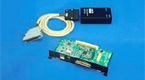
| Composition | Dedicated expansion board, relay cable, IrDA probe pod, 3-wire probe cable |
(*1) Restricted by analyzer performance.
(*2) Set from analyzers.