(For LE-8200A/8200)
LE-PC800G
LE-PC800G is a Windows® software which allows you to remotely control the protocol analyzer from your PC and utilize the analyzer measurement data on your PC. You can also read the measurement log file of the communication analyzer sent by e-mail or USB flash memory and analyze it on a PC or convert it to text/CSV format.
Applicable analyzers: LE-8200A, LE-8200
- Multiple analyzers can be controlled at the same time.
- Easy operation of key emulation
- Communication log can be continuously saved up to 256Gbyte by the remote monitor function.
- Various kinds of display depending on the protocols such as SDLC, X.25, PPP, and MODBUS
- Collective conversion into Text format/CSV format
- Automatic switching of Japanese/English
"LE-PC800G (light edition)" which has some limitations can be downloaded free of charge.
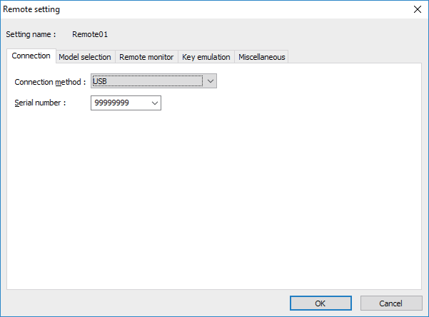
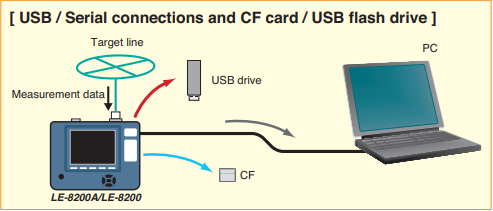
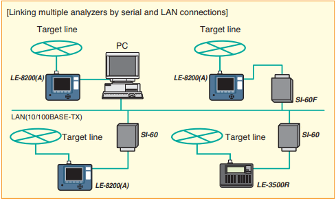
Supports multi-link and remote measurement via USB connection, serial connection, etc.
Depending on the communication analyzer to be connected, USB connection, COM port connection, wired LAN connection via LAN ⇔ serial converter can be used. You can remotely control multiple analyzers by linking them from a PC at the same time and execute measurement.
Connection setting
It also supports display of measurement data in the memory card and data conversion.
[ In addition to the real-time data transfer, copying by external memories is also available. ]
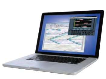
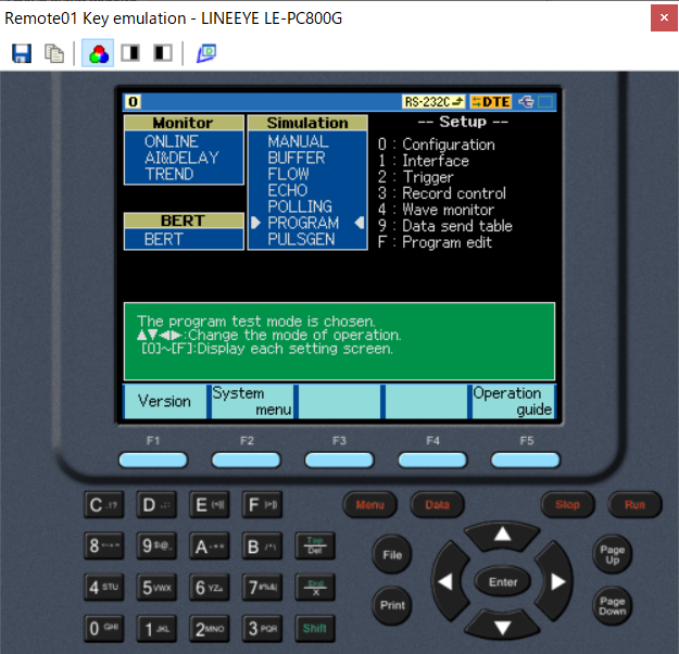
Emulates the operation of the analyzer on the personal computer
A key emulation function is provided to reproduce the familiar analyzer display and operation on a PC. It allows remote control as if operating the analyzer directly from a PC.
[ Key emulation display example ]
Remote monitor function
The remote monitor function captures the log data from operating analyzer and records it on its hard disk or SSD, and at the same time it displays the data on the PC's screen. Depending on the purpose of use and the capacity of the storage, you can specify the size of each log file by "Block size" and the maximum number of log files by "Maximum block count". When you want to stop the logging automatically at the specified capacity you can use fixed buffer mode, and when you want to log the data continuously keeping its latest log data you can use the ring buffer mode.
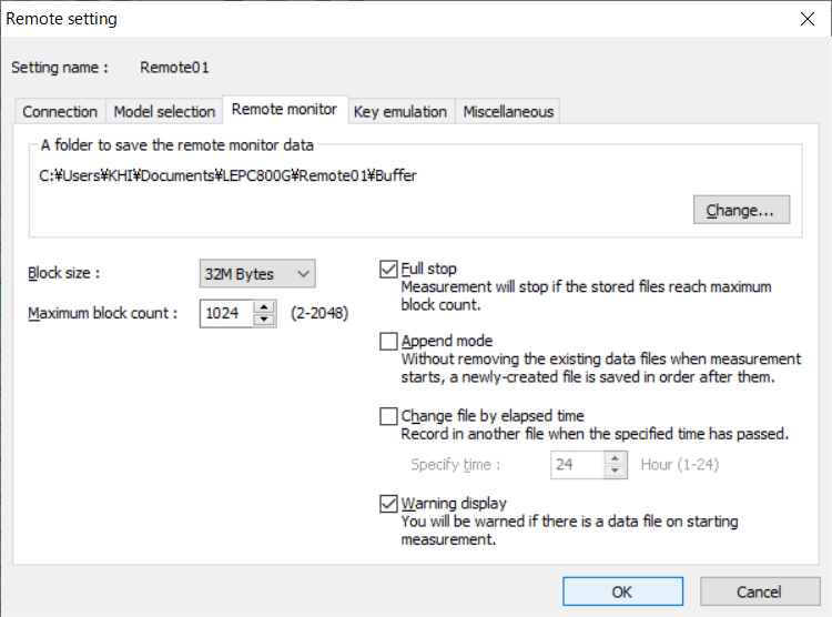
Block size 1M/2M/4M/8M/16M/32M/64M/128M bytes
Maximum number of blocks 2 to 2048
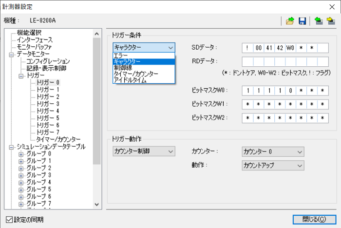
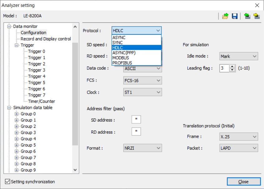
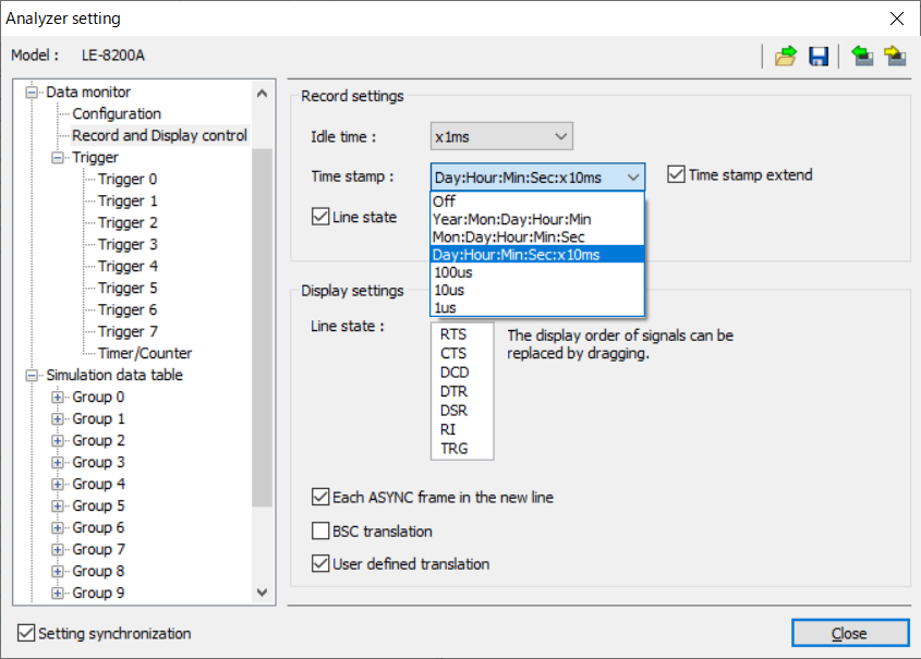
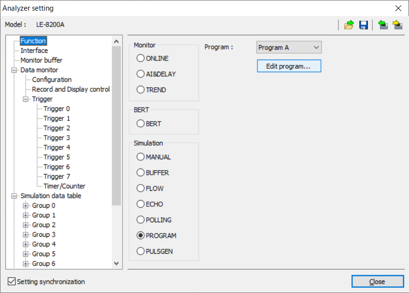
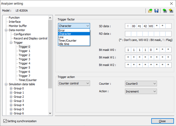
Synchronizes the configuration with the analyzer
The configuration and the analyzer setting set on the PC software can be synchronized with that of the analyzer in remotely connected.
Communication setting
Record setting
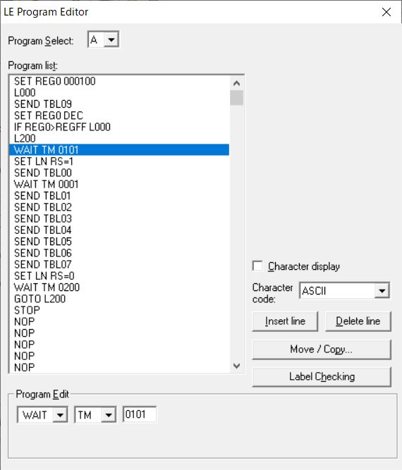
Simulation setting
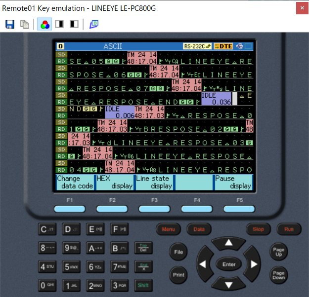
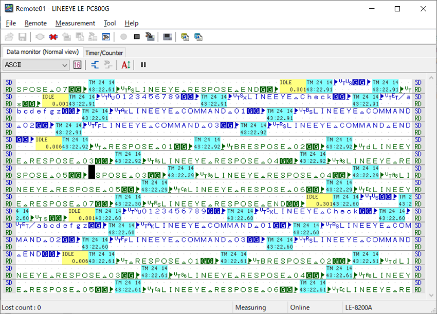
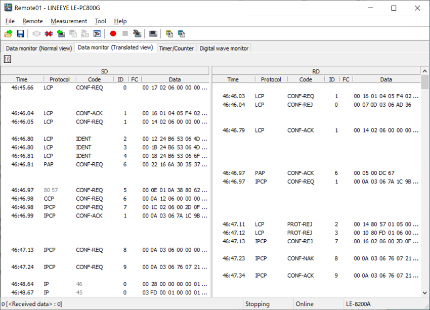
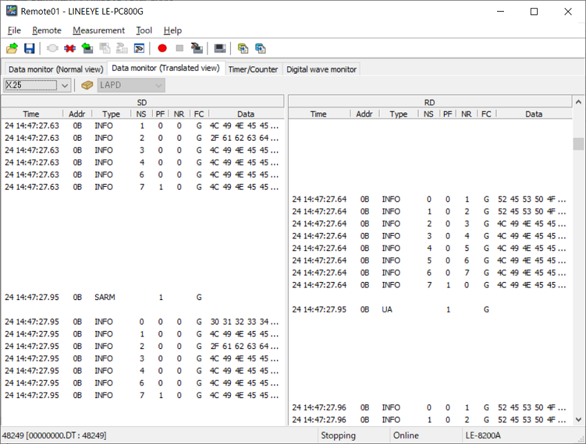
Large screen and various kinds of display
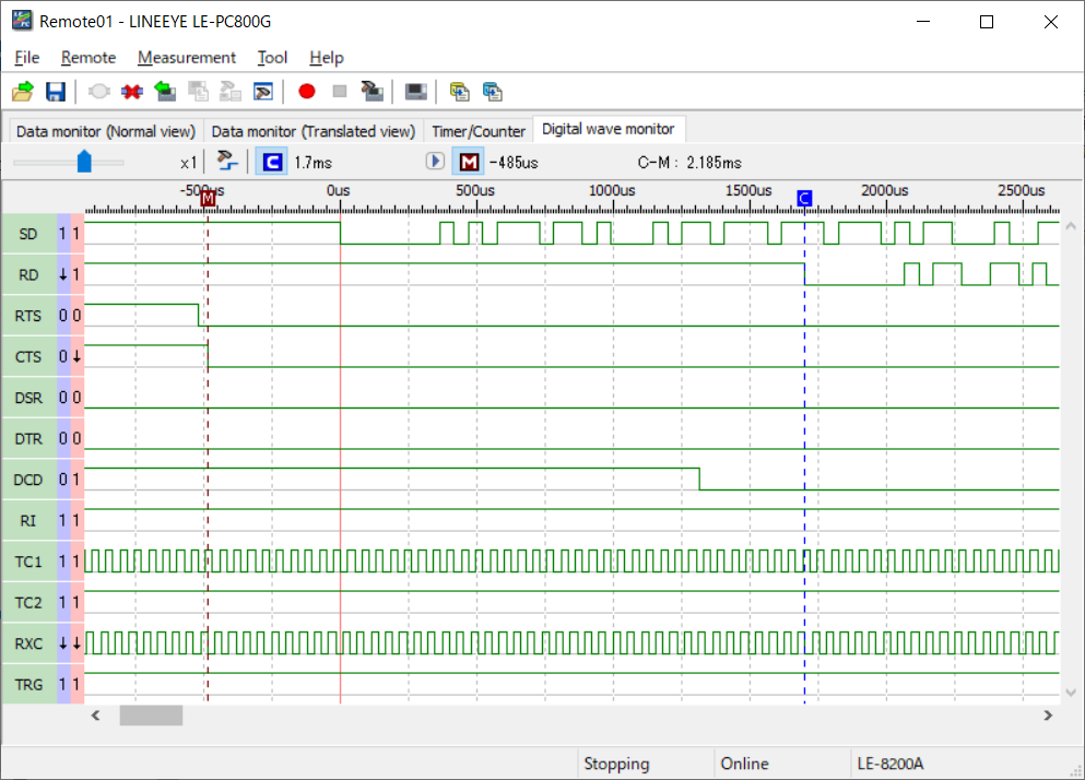
This function allows you to switch the display mode: raw data display, protocol translation display, and logic analyzer waveform display.
PPP translation display
HDLC translation display
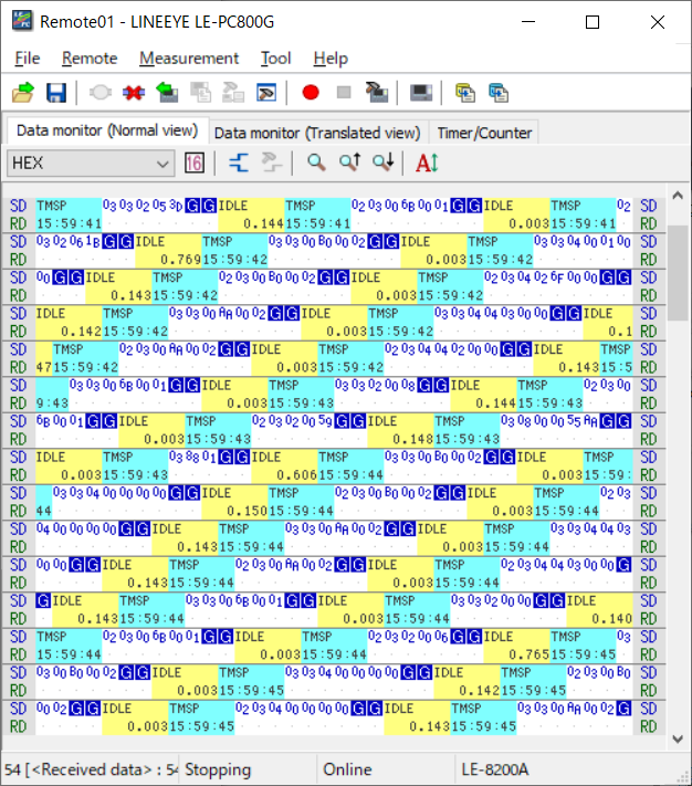
Modbus normal display
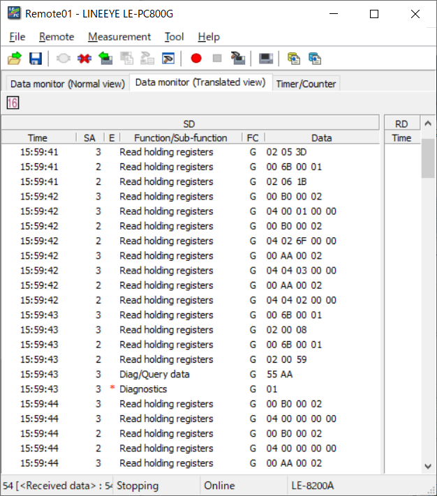
Modbus translation display
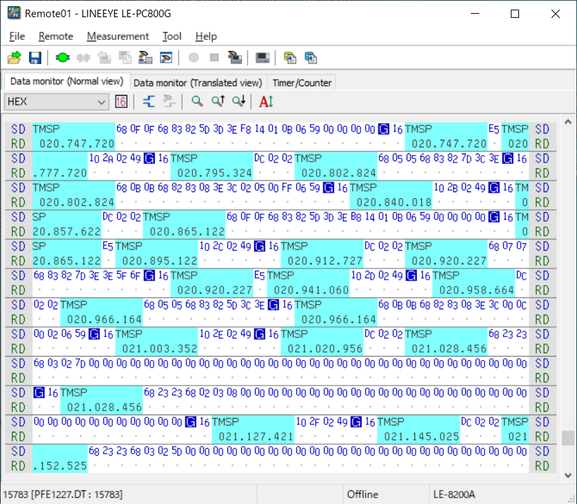
PROFIBUS normal display
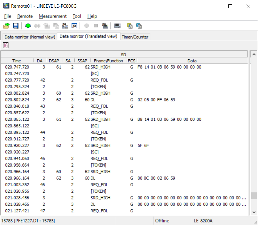
PROFIBUS translation display
Logic analyzer display mode
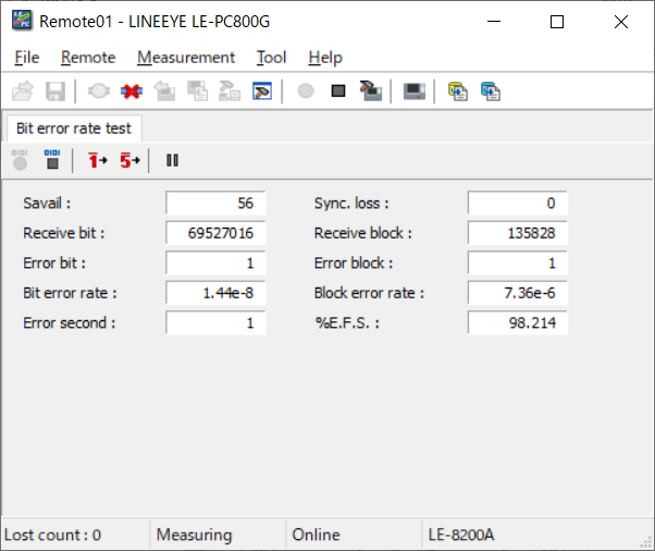
BERT mesurement mode
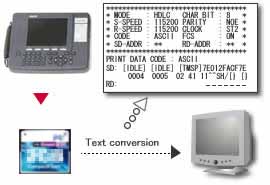
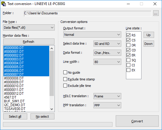
Converts the stored data to a text or CSV format all together
This function allows you to convert into a text or CSV format the data stored by the remote monitor function or stored in a memory card by an analyzer all together.
Converts data stored on a memory card to the text/CSV format.
Text conversion setting
Changes the system language automatically (Japanese/English)
The system language alternates automatically between English and Japanese according to that of OS. This facilitates introduction of the software to development bases outside Japan.
English
Japanese