Multi Protocol Analyzer
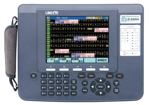
LE-8200A
●Records data in the USB drive
●Battery Powered Handheld Troubleshooter for Field Testing
●5.7-inch TFT color display
●Supports TTL, I2C, SPI, IrDA,
●CAN, LIN, FlexRay, LAN and USB
●Mega Speed Mesurement
●Supports Logic Analyzer Analysis and Analog Waveform Analysis
●Outputs edited digital waveform.
The LE-8200A is the top-level model of battery-powered communications protocol analyzer. The LE-8200A has an enlarged display in response to an increasing demand without degrading the excellent portability of the LE Series. It is ideal for development tests of communications systems and industrial equipment, as well as for after-sale services and communication trouble analysis. LE-series have been used in the industries of railways, aviation, and a variety of manufactures for few decades where reliability is very important. With optional kits, it can be used for developing network, in-vehicle, PC peripheral, embedded devices. Unlike the software based analyzers, it cannot be affected by the capability of PC and can be used in the place where PC is not allowed.


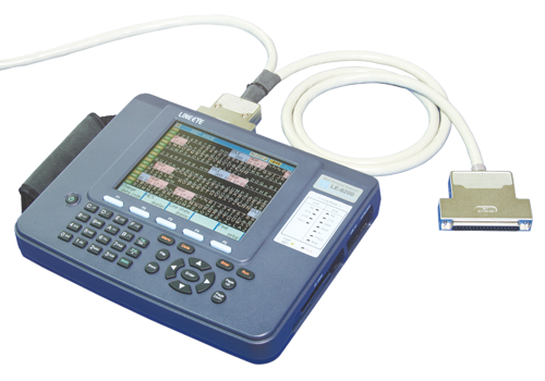
| Interface (standard) | RS-232C (V. 24), RS-422/485 (RS-530) |
|---|---|
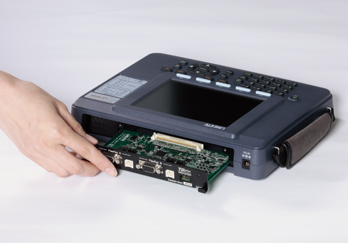
| Expansion measurement interface*1 | RS-422/485 terminal block [LE-25TB], X. 20/21 [LE-25Y15], RS-449 [LE-25Y37], V. 35 [LE-25M34], 1.8/2.5/3.3V/5V TTL/I2C/SPI [OP-SB85L], Infrared communication IrDA/ASK [OP-SB85IR], Current loop [OP-SB85C], CAN/LIN [OP-SB87] , FlexRay [OP-SB88], LAN [OP-SB89], Gigabit Ethernet [OP-SB89G], USB [OP-SB84] |
| Standard Protocol | ASYNC (Asynchronous), ASYNC-PPP, Character synchronous SYNC/BSC, Bit synchronous HDLC/SDLC/X. 25, Modbus, PROFIBUS |
| Optional Protocol | I2C, SPI, BURST*2, IrDA(IrLAP), CC-LINK, CAN, Devicenet, LIN, FlexRay, LAN, USB |
| Synchronous clock | ST1 (DTE transmission clock), ST2 (DCE transmission clock), RT (DCE reception clock), AR (The synchronous clock extracted from the edge of the transmission and reception data) |
| Capture memory*3 | Capacity : 100MB It is composed of DDR-SDRAM of which allows high-speed access. Two separated screens. Auto backup.*4 Error erasure prevention. Choose ring buffer or fixed size buffer. |
| Backup memory | Capacity:4MB It can be saved the measurement data and conditions by the built-in lithium battery for 10 years. |
| Max. speed | Full duplex: 2.150Mbps / Half duplex: 4.000Mbps |
| Speed setting range | 50bps to 4.000Mbps Freely set to four effective digits, separately for transmission and reception. (Margin of error: 0. 01% or less) |
| Expansion speed (HDLC mode) | 115.2Kbps to 12Mbps [OP-FW12G] |
| Data format | NRZ, NRZI, FM0, FM1, 4PPM, ASK, Manchester0, Manchester1 |
| Data code | ASCII, EBCDIC, JIS7, JIS8, Baudot, Transcode, IPARS, EBCD, EBCDIK, HEX |
| Character framing | ASYNC : data bit (5, 6, 7, 8) + parity bit (0, 1) + stop bit (1, 2) Character synchronous : data bit + parity bit (6 or 8bits in total) Bit synchronous : data bit (8bits) |
| Parity bit | NONE, ODD, EVEN, MARK, SPACE |
| Multiprocessor bit | MP (multiprocessor) bit is shown with a special mark. |
| Bit transmission order | LSB first or MSB first (switchable) |
| Polarity inversion | Normal, Invert (switchable) |
| Error check | Parity (ODD, EVEN, MARK, SPACE), Framing, Break, Abort, Short frame, BCC (LRC, CRC-6, CRC-12, CRC-16, CRC-ITU-T, FCS-16, FCS-32). BCC permeation mode . |
| Online monitor function | Communication log is recorded continuously and displayed in the LCD without affecting the communication lines. |
| Idle time display | OFF (no record); Resolusion: 100ms, 10ms, 1ms; Max 999. 9 sec |
| Time stamp display | Time stamp: "Day/Hr/Min", "Hr/Min/Sec", "Min/Sec/10ms". Expanded time stamp: "Yr/Mon/Day/Hr/Min", "Mon/Day/Hr/Min/Sec", "Day/Hr/Min/Sec/10ms"; Elapsed time stamp: "100us/10us/1us"; OFF (no record) |
| Line status display | Records and displays the wave form of 7 signals (chosen from RS(RTS), CS(CTS), ER(DTR), DR(DSR), CD(DCD), CI(RI), TRGIN(external trigger input) along with the transmission/ reception data |
| Address filter | Records only frames of the specified address. (only when HDLC/SDLC/X.25) |
| Data display and operations | Pause in capture, two seperated screens, scroll, paging, jump to the specified screen . |
| Bit shift display | Entire frame can be shifted to the right or left in 1 bit increments . |
| Protocol translation display | SDLC (modulo 8/128), ITU-T X.25 (modulo 8/128), LAPD, PPP, BSC, IrLAP, I2C, User Defined Translation |
| Line status LED | Two color LEDs of SD, RD, RS(RTS), CS(CTS), ER(DTR), DR(DSR), CD(DCD), CI(RI), ST1(TXC1), ST2(TXC2), RT(RXC) |
| RS-232C | Logic ON (red) , logic OFF (green) , no connection NC (light off) |
| Other I/F | Logic ON (red) , logic OFF or no connection NC (light off) |
| Interval timer | 4kinds; Max. count: 999999 (Resolution: 1ms ,10ms ,100ms) |
| General-purpose counter | 4kinds; Max. count: 999999 |
| Data counter | For SD and RD (1 each): Max. count: 4294967295 |
| Trigger function | Up to 8 pairs of trigger condition and action can be specified. (sequential action, which validates another condition after one condition satisfied, is also possible.) |
| condition | Communication errors (parity, MP, framing, BCC, break, abort, short frame can be specified individually.), communications data string up to 8 characters (don't care and bit mask available), idle time more than the specified duration, match time,/counter value, logic status of interface signal line, external trigger input |
| action | Stops measurement/test (offset can be set), validates trigger condition: controls timer (start/stop/restart), controls counter (count/clear), activates buzzer , saves monitor data on a memory card, sends the specified character string (during manual simulation), sends pulse to external signal |
| Data search function | Retrieves the data with specific condition from capture memory. |
| condition | Communication error (Parity, MP, framing, BCC, break, abort, short frame),communication data string up to 8 characters (don't care and bit mask available) , idle time more than the specified duration, specified timestamp (don't care available), trigger matching data . |
| action | Shows the match data at the top or enumeration display (selectable) |
| Monitor conditions auto setting | Measurement conditions such as protocol, transmission speed, (max. 115.2Kbps), data code, synchronous character and BCC check can be set . |
| Auto run/stop function | Enables measurement to start and end at the specified time at the selected repeating cycle (monthly, daily, hourly) . |
| Auto save function | Automatically saves the monitored data in the capture memory and saves as communications log file in the External memory. |
| File size | BUF (capture memory size) , 1MB , 2MB , 4MB , 8MB, 16MB , 32MB , 64MB |
| MAX. files | 2048 |
| Delay time function | Measures and displays the interval of change in the interface signal line. (current/min/max/average, resolution: 0. 1ms) |
| Signal voltage measuring function | Measures and displays the value of voltage amplitude: SD, RD, ER(DTR), external signal EXIN. (current/min/max, range 15V resolution : 0.1V) |
| Statistical analysis function | Takes statistics the numbers of frames, transmission/reception data, and satisfied trigger condition for a specified period (1-240 min. or 1-240 sec.) And display them in graphs. |
| Logic analyzer function | Measures the logical change of the interface signal in the sampling clock period, and displays its wave. |
| Sampling clock | 1KHz to 100MHz (15 steps) |
| Sampling memory | Min 4,000 |
| Trigger condition | Trigger conditions in the ONLINE monitor functions match. Logical status match between interface signal line and external signal . |
| Trigger position | Before, center, after |
| Zoom in/out | x10, x5, x2, x1, x1/2, x1/4, x1/8, x1/16, x1/32, x1/64 |
| Other functions | Time measurement by cursor, signal line exchange, signal status search |
| Bit error rate test | At DTE or DCE mode (It is possible to change of the pin arrangement ), line quality measurement test such as error rates can be done by loop back test or interactive test. |
| Communication mode | Synchronous (SYNC), Asynchronous (ASYNC) Able to have RTS/CTS flow control |
| Measuring speed | 50bps~4. 000Mbps, freely set to four effective digits |
| Measurement mode | Continuous measurememt, specifies the number of receiving bit, specifies the time to measure, repeatedly measurement at the unit of 1 - 1440 |
| Test pattern | 26-1, 29-1, 211-1, 215-1, 220-1, 223-1, MARK, SPACE, ALT, DBL-ALT, 3in24, 1in16, 1in8, 1in4 |
| Error bit insertion | Inserts 1-bit or 5-bit error in test pattern by key operation. |
| Measurement range | It is able to measure the parameter of the ITU-T advice G.821. Effective received bit (0 to 9999999 to 9. 99E9), bit errors (0 to 9999999 to 9. 99E9), bit error rate(0 to 9. 99E-9 to 1), block errors (0 to 9999999 to 9. 99E9), block error rate (0 to 9. 99E-9 to 1), Savail(available measurement time: 0 to 9999999sec), loss count (synch loss: 0 to 9999), error duration (0 to 9999999sec), %EFS (normal operation rate: 0. 000 to 100. 000%) |
| Simulation function | Enables transmission/reception test of any given data in DTE or DCE mode (selectable with pin assingnment). |
| Transmit data entry | Can be registered in 160 types of transmission data tables (16 for each 10 groups, Total of 16 K data). |
| Error data entry | A part of transmission data can be registerd as error data such as parity error. |
| Line control mode | Auto (Controls transmission timing with RS(RTS), CS(CTS), ER(DTR), CD(DCD) signal lines automatically in 1 ms increments) or manual (key operation) can be selected. |
| Transmit driver control | Auto control (Turns ON driver only before and after data transmission) or manual mode (link with ER(DTR), CD(DCD) key operation) can be selected during simulation of RS-485. |
| Half-duplex mode | Can sort the sending data of the analyzer and the receiving data of opposite device to SD and RD. |
| MANUAL mode | Sends the data assinged to operation keys each time a key is pressed, while checking communications status on the display. Can be used together with the trigger function. |
| FLOW mode | Simulates the X-on /X-off control data and flow control procedures of RTS/CTS control line. (Sender and receiver selectable). |
| ECHO mode | Sends the received data frame by frame (buffer echo), by data (character echo) or by loop back. |
| POLLING mode | Simulates polling communications procedures. (Sender and receiver selectable) |
| BUFFER mode | Reproduces transmission of selected data (SD or RD) captured in memory by monitor function. |
| PROGRAM mode | Creates a simulation program (Max. type: 4, Max steps: 512) using the dedicated commands (47 types) to test the communication procedure. |
| PULSGEN mode | It regenerates the timing waveform on a communication line, which captured by the logic analyzer function. |
| File management function | Measurement data and condition can be saved in the CF card or USB flash drive . And the format of the data/condition can be used in the PC. |
| File types | Measurement data (.DT ), measurement condition (.SU), trigger save data (TG SAVEnn.DT), auto save data (#nnnnnnn.DT), auto back-up data(@AUTOBU0/1/2.DT) |
| File controls | Normal file display, sort display, file display by specified type, save, load, delete, delete all, format |
| Memory card | 512M byte to 128G byte CF card (only the LINEEYE guarantees to use) / MAX 128G byte USB flash drive |
| Printout function | Measurement data can be printed in various formats. Text files can be saved in the external memory. Screen image can be printed and saved in the external memory. |
| LCD | 5.7 inch TFT color liquid crystal display. 320 x 240 dot. LED back light can be adjusted. |
| AUX(RS-232C) port | Mini DIN8 pin connector. Communication speed: 9600bps to 230.4Kbps (6 steps) Print out data, Can be used with PC [LE-PC800G], Can be used to upgrade the firmware. |
| USB2.0 device port | B-connector in device side. Transfer data in high-speed. Can be used with PC [LE-PC800G], Can be used to upgrade the firmware. |
| USB2.0 host port | Host side: Type A connector
It supports high-speed transfer This is for the connection to a USB flash drive. |
| Power supply | Built-in nickel hydrogen battery or AC adapter DC9V, 2A(AC100 ~ 240V), 50/60Hz. |
| Battery operating time*5 | About 4 hours Power saving mode: Auto back light off, Auto power off (It will not work while measuring.) |
| Battery charging time | About 2.5 hours |
| Ambient temperatures | In operation : 0 to 40 degree Celsius, In storage : -10 to 50 degree Celsius |
| Ambient humidity | In operation : 20~80%RH (No condensation), In storage : 10~85%RH (No condensation) |
| Standard | CE(class A), EMC(EN61326-1 : 2013) |
| Dimension*6, mass | 240 (W) x 190 (D) x 48 (H) mm , about 1.1Kg |
| Accessories | Monitor cable for DSUB 25-pin (LE-25M1), AUX cable for DSUB 9-pin (LE2-8V), external signal I/O cable(LE-4TG), AC adapter(6A-181WP09), carrying bag(LEB-01), Hand strap, Line state sheet, Utility CD, instruction manual and warranty |
*1: To have the function, optional accessory described in "[ ]" is need.
*2: Mode in which all data is imported in synch with clock edge.
*3: Only 1M of capture memory will be backed up by the battery. Transmission/reception data, idle time, time stamp, line status consume 4 bytes of memory at each capture.
*4: This function automatically saves the measurement data in the CF card or back up memory, when the measurement end.
*5: Under the normal operation.
*6: Hand strap is not contained.