A PC-connectable communication protocol analyzer, which can also be used
as a stand-alone communication data logger that supports SD cards
LE-150PS
Async Communication Supported
Two Types of Operations Based on Usage Situation.
This device can be used as a PC-connectable Protocol Analyzer for use in the lab (Remote mode), and also as a PC-less Data Logger for use a ton-site tests to record data for long hours (Logger mode).
<Remote Mode>  |
<Logger Mode> |
Supports RS-232C/RS-422/RS-485 (Standard Feature)
The device comes standard with RS-232C/RS-422/RS-485 interfaces, which are used widely in medical equipment and electronic products.
RS-232C interface supports 8 lines including control lines and it is able to operate the control lines automatically at Simulation function. RS-422/485 interface is able to control the driver automatically at Simulation function.
Explanation of each part
switch
Connector

slotUSB connectorDC
switchSD card slotUSB
|
* For attaching the optional DIN rail plate.
Pitch: 70mm. Depth: 3.5mm (max). * Above picture is the LE-200PS. (Specification of each part is same in LE-150PS and LE-200PS.)
|
Pin Assignment of Connector (DSUB 25pin)
*1: A terminal-supplied power from analyzer. ON/OFF switchable.
*2: LE-5TB is useful for connecting the signals.
Do not allocate power supply of more than 6V to its 9/10/11/18/19 pin on the Dsub 25pin connector. It may cause the product malfunction. |
RS-485 Connection ImageTerminal Block Adapter (LE-5TB) 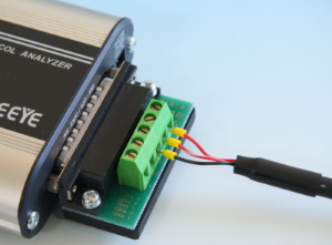
Connection of Terminal Block Adapter (LE-5TB)
|
Supprts TTL level communication with an option.
With an optional TTL probe pod (OP-5M), it can monitor TTL-level communication at 2.5V/ 3.3V/ 5V. It is useful such as when measuring TTL signals on an UART port of PCB and communication units.
Support Async PPP communication
Support Async and PPP communications. It is possible to select bit transmission order, polarity, and data format (NRX/NRX) and able to analyze efficiently.
Trigger Configuration (Example 1)
In this setting, if finding an error, “1” will be added in the “Conter1”. Details of counters can be checked by selecting Timer/Counter window. And, the value of counter can be another trigger condition.
Trigger Configuration (Example 2)
In this setting, if finding data of “41h, 42h, 43h, 15h”, LED of U1 will be lighted. It is useful to check the flowing of specific data on the line without stopping the measurement.
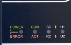 |
Lights of LED stands for:
|
Long Hour Recording
[Recording Time]
| Baud Rate | Capacity: 2G byte (e.g. 2M byte×100 files) |
|---|---|
| 9600bps | Approx. 120 Hours |
| 230.4Kbps | Approx. 5 Hours |
Measured data is saved as log files of the specified file size in the HDD of the PC (Remote mode) or in the SD card of the analyzer (Logger mode).
It automatically records data until reaching the specified number of files, and then deletes the oldest file to record the new file. Also, it can stop measurement on reaching the specified number of files. It is useful for detecting any hindrance in the line.
Measures at Arbitrary Speed
Monitor data at any speed by setting the baud rate of any four digits.
The high-precision timer makes it possible to record idle time and time stamps along with data, and is not related to the performance of the PC.
Easy-to Operate Simulation Function
It incorporates an easy-to-use simulation function that makes it possible to transmit preset transmission data (16 types of data), or fixed data such as FOX messages, at the flip of a key while checking reception data.
<Example of Simulation>
Schedule Measurement by Inner RTC
Real Time Clock (RTC) backed up by the battery of the analyzer makes it possible to specify the starting and ending times of the measurement. After the measurement, it turns off the power automatically and saves on power consumption.
Example of Use 1
Measure while the factory runs operation from 9:00 to 17:30.
| Saving Mode | Append |
|---|---|
| Max Files | 450 |
| File Size | 4M |
| Mode | Daily |
| Run Time | 9:00 |
| Stop Time | 17:30 |
| Power On Run | off |
LED of LE-150PS will start blinking at 8:59 and be ready for measurement. It will start measuring at 9:00 and record data in the SD card for 450 files (4M each) as a ring buffer. It will stop measuring at 17:30 and turn off the power automatically to save on power consumption.
Example of Use 2
Equipment communicates with other equipment while it receives power from a power supply randomly.
| Saving Mode | Append |
|---|---|
| Max Files | 500 |
| File Size | 1M |
| Mode | Daily |
| Run Time | non |
| Stop Time | non |
| Power On Run | on (safety start) |
In this care, it is necessary to prove power to the LE-150PS from the same power supply for the equipment.
Safety start will start measuring approximately 40 seconds (LED will be blinking) after powering on the analyzer for charging the capacitor for back-up data.
Communication logs will be saved in the SD card for 500 files (1M each) endlessly. LE-150PS will stop measuring when the power is not supplied for more than 1 second after saving data in the SD card.
Seamless Access to Communication Log Files
Communication log files can be viewed in detail on a PC. It offers seamless operation that handles a single measurement log file even when all files are read collectively. The measured data can be converted into text or CSV format to use in a word processor and/or spreadsheet software.
*===============[2012-06-06 00:02:00]=*
* Model     : LE-150PS                *
* Version   : 1.06                    *
* Serial No.: ********                *
* Start time: 2012-06-06 00:00:00     *
* Stop time : 2012-06-06 00:01:00     *
*-------------------------------------*
* MONITOR DATA                        *
*  PROTOCOL: ASYNC                    *
*  S-SPEED : 9600    R-SPEED : 9600   *
*  CODE    : ASCII   CHAR BIT: 8      *
*  PARITY  : NONE    STOP BIT: 1      *
*  BCC     : NONE                     *
*                 PRINT CODE : ASCII  *
*=====================================*

SD:[ IDLE ][ TMSP ] - - - - - - - - - - - - - - - - - - - -
   [ 0384 ][060810]
RD:                3131323030303030323036303133303031303030
                    1 1 2 0 0 0 0 0 2 0 6 0 1 3 0 0 1 0 0 0

SD: - -[ IDLE ][ TMSP ]06[ IDLE ][ TMSP ] - - - - - - - - -
       [ 0015 ][060810]AK[ 0467 ][060811]
RD:0D0A                 -                313132303030303032
   CRLF                                   1 1 2 0 0 0 0 0 2

SD: - - - - - - - - - - - - -[ IDLE ][ TMSP ]06[ IDLE ][ TM
                             [ 0015 ][060811]AK[ 0411 ][060
RD:30373031333030313030300D0A                 -
    0 7 0 1 3 0 0 1 0 0 0CRLF

SD:SP ] - - - - - - - - - - - - - - - - - - - - - -[ TMSP ]
   812]                                            [060812]
RD:    31313230303030303230383031373730313030300D0A
        1 1 2 0 0 0 0 0 2 0 8 0 1 7 7 0 1 0 0 0CRLF

SD:15[ IDLE ][ TMSP ] - - - - - - - - - - - - - - - - - - -
   NK[ 4725 ][060820]
RD: -                31313230303030303230393031373530313030
                      1 1 2 0 0 0 0 0 2 0 9 0 1 7 5 0 1 0 0

SD: - - -[ IDLE ][ TMSP ]06[ IDLE ][ TMSP ] - - - - - - - -
         [ 0072 ][060820]AK[ 0651 ][060821]
RD:300D0A                 -                3131323030303030
    0CRLF                                   1 1 2 0 0 0 0 0
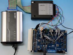
Control multiple analyzers by one PC software.
PC link software (LE-LINK20) included with the product controls multiple analyzers at the same time, and displays data in the separate measurement windows.
Can be used in Various Situation
Protects Important Data from Corruption due to Power Failure
A newly developed Instant Power Failure Prevention circuit with a Super Capacitor protects important communication log files stored in the SD cards. It protects data in case it occurs the power failure during recording to the SD card. Also, you can select the restart method of measurement from "Instant Start" or "After Charging Super Capacitor". Thus, continuous recording is possible while considering the status of data generation and power system.
[Acquired Patent in Japan]
Small and Robust Housing Suitable for Severe Field Environments
< Dust-proof covers >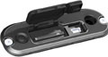 |
< DIN Rail Installation Example > 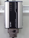 |
The palm-sized robust unit can be used between –10 to +55°C. It operates not only on USB bus power, but also on external DC power of 8 to 26.4V. The consumption current is as low as 100mA at DC12V input. The SD card slot and the USB connector are equipped with a dust-proof cover that allows 2-way operation. It can be fixed easily to the equipment to be examined or built into an inspection line, since it is compatible with 35mm DIN rails.
Automatically Switches between Japanese and English
The system language alternates automatically between English and Japanese according to that of OS. This facilitates introduction of the software to development bases outside Japan.
Specifications
In the Logger mode (PC less), you need to have the optional AC adapter (6A-181WP09) or use the optional Power Plug Cable (SIH-2PG) and external DC power.